Mobile radio terminal

Inactive Publication Date: 2006-03-21
FUJITSU CONNECTED TECH LTD
View PDF14 Cites 14 Cited by
  • Summary
  • Abstract
  • Description
  • Claims
  • Application Information

AI Technical Summary

Benefits of technology

[0007]The present invention has been made in consideration of the above problem, and its object is to provide a mobile radio terminal which is very convenient when an incoming call has been received during reproduction of a moving picture.
[0010]Thus, according to the mobile radio terminal with this structure, call reception can surely be indicated to the user, and display of a moving picture is suspended only temporarily. Thus, the display can smoothly be resumed, which is convenient for the user.
[0013]Thus, according to the mobile radio terminal with this structure, when call reception has occurred while the moving picture is being reproduced, the reproduced image is not changed to an image that only indicates the call reception, and the user can conveniently recognize the occurrence of the incoming call.

Problems solved by technology

In the meantime, with the conventional mobile radio terminal, there is a problem of how an incoming call, when received during reproduction of a moving picture, is indicated.

Method used


Image

  • Mobile radio terminal
  • Mobile radio terminal
  • Mobile radio terminal

Examples


first embodiment

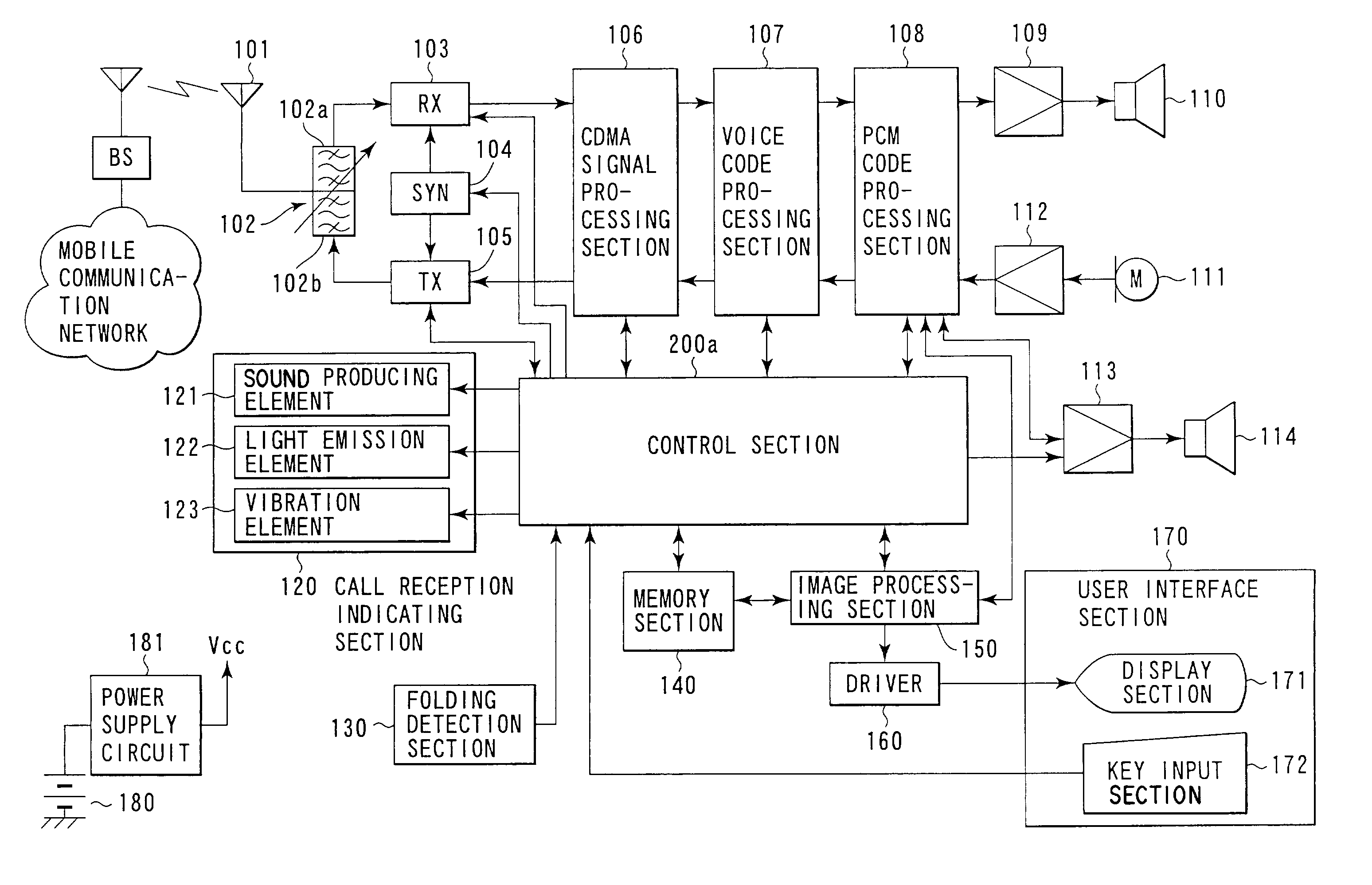
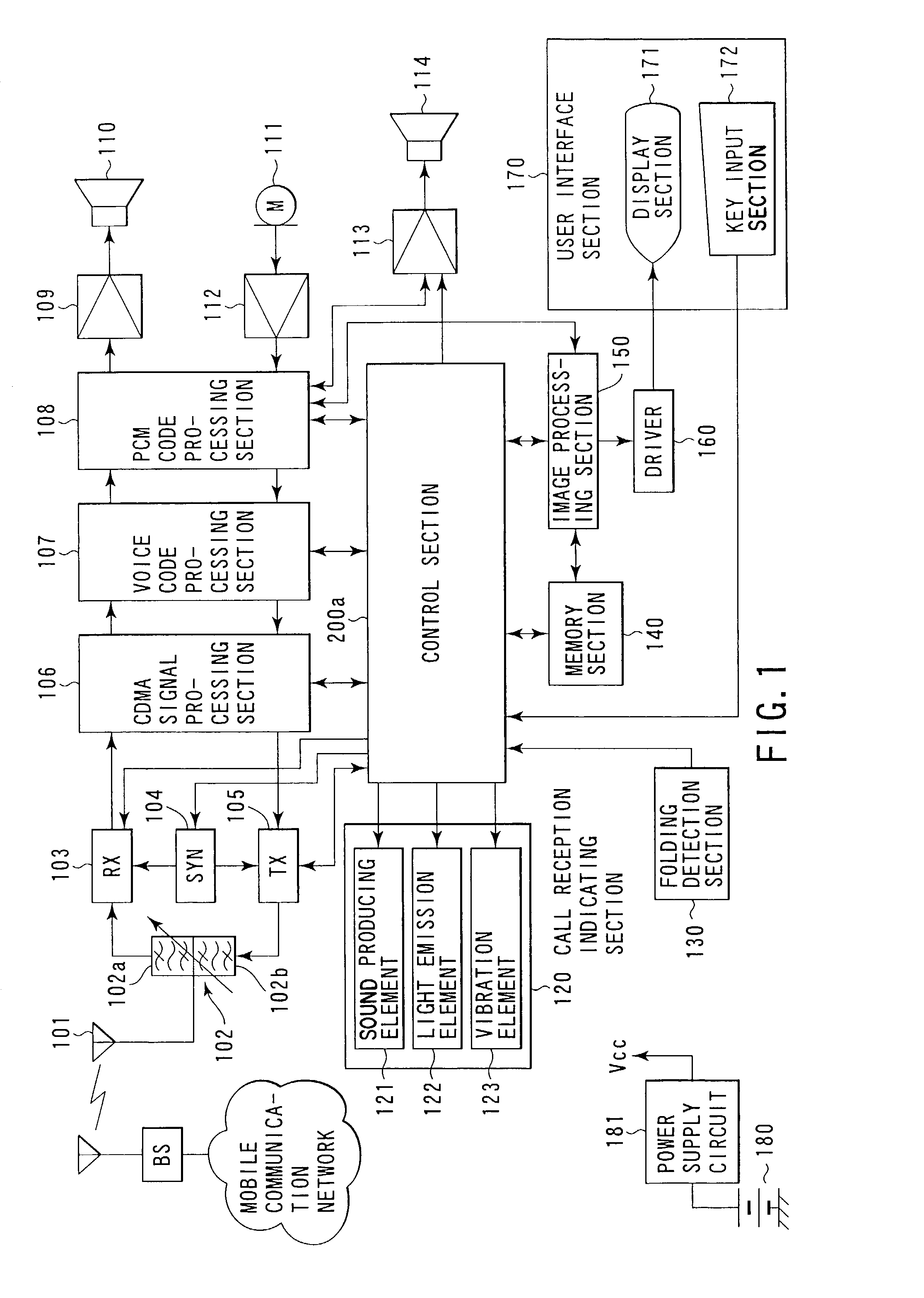
[0026]FIG. 1 shows the structure of a mobile radio terminal according to the present invention. The mobile radio terminal shown in FIG. 1 performs, for example, radio communication with a base station BS by CDMA (Code Division Multiple Access).

[0027]The base station BS transmits a radio frequency signal, and an antenna 101 receives the radio frequency signal. The radio frequency signal is then input to an antenna shared device 102. The antenna shared device 102 comprises a filter 102a for reception and a filter 102b for transmission.

[0028]Of radio frequency signals received by the antenna 101, the radio frequency signal sent from the base station BS passes through the reception filter 102a and goes to a receiving section (RX) 103. This radio frequency signal is prevented by the transmission filter 102b from going to a transmission section 105 (to be described later).

[0029]In the receiving section 103, the radio frequency signal is mixed with a reception local oscillation signal supp...

second embodiment

[0101]A mobile radio terminal according to the present invention will now be described.

[0102]FIG. 5 shows the structure of this mobile radio terminal. The mobile radio terminal shown in FIG. 5 performs, for example, radio communication with a base station BS by CDMA (Code Division Multiple Access).

[0103]The base station BS transmits a radio frequency signal, and an antenna 101 receives the radio frequency signal. The radio frequency signal is then input to an antenna shared device 102. The antenna shared device 102 comprises a filter 102a for reception and a filter 102b for transmission.

[0104]Of radio frequency signals received by the antenna 101, the radio frequency signal sent from the base station BS passes through the reception filter 102a and goes to a receiving section (RX) 103. This radio frequency signal is prevented by the transmission filter 102b from going to a transmission section 105 (to be described later).

[0105]In the receiving section 103, the radio frequency signal ...


PUM


Abstract

An image processing section reads out moving picture data from a memory section in accordance with an instruction from a control section, and subjects the moving picture data to a predetermined data process and converts it to image data and voice data. Based on the image data, a driver drives a display section for display control. The control section controls respective parts of a mobile radio terminal. Even while a moving picture is being reproduced, if call reception occurs, the control section temporarily suspends the reproduction of the moving picture and indicates the occurrence of call reception. If the call ends, the control section resumes the reproduction of the moving picture.

Description

CROSS-REFERENCE TO RELATED APPLICATIONS[0001]This application is based upon and claims the benefit of priority from the prior Japanese Patent Applications No. 2001-305768, filed Oct. 1, 2001; and No. 2002-235832, filed Aug. 13, 2002, the entire contents of both of which are incorporated herein by reference.BACKGROUND OF THE INVENTION[0002]1. Field of the Invention[0003]The present invention relates generally to a mobile radio terminal capable of communication via a mobile communication system such as a mobile telephone system, and more particularly to a mobile radio terminal with a moving picture reproducing function.[0004]2. Description of the Related Art[0005]A modern mobile radio terminal such as a mobile phone has a function of reproducing a moving picture or voice. With such information being heard or viewed by a user, a great deal of information can be communicated.[0006]In the meantime, with the conventional mobile radio terminal, there is a problem of how an incoming call, w...

Claims


Application Information

Patent Timeline
Patent Type & Authority Patents(United States)
IPC IPC(8): H04M1/00H04M1/724H04M1/57
CPCH04M1/72519H04M1/57H04M1/724
Inventor KUROKAWA, OSAMUFURUSAWA, MASAAKIIGARASHI, JUNICHIWAGAI, KIYOSHITSUKUI, YASUHIRO
Owner FUJITSU CONNECTED TECH LTD
Why Eureka
Try Eureka