Telemetry antenna for an implantable medical device

a technology of telemetry antenna and medical device, which is applied in the direction of electrotherapy, heart stimulators, therapy, etc., can solve the problems of increasing the complexity of programmable operating modes, attenuating the rf field, and menus, etc., and achieves low error rates, low power consumption, and high data bit rate

Inactive Publication Date: 2006-03-21
MEDTRONIC INC
View PDF21 Cites 77 Cited by
  • Summary
  • Abstract
  • Description
  • Claims
  • Application Information

AI Technical Summary

Benefits of technology

[0031]The IMD header can comprise a connector header that includes connector bores for receiving and header connector elements for making connection with proximal lead connector elements of electrical medical leads. The header connector elements are coupled through connector feedthrough pins of connector feedthroughs mounted to a side of the hermetically sealed enclosure, the connector feedthrough pins extending into the hermetically sealed housing and coupled to electrical circuitry of the IMD. Advantageously, the antenna feedthrough is located away from these connector components, and the connector components are located between the second antenna element and the second minor side of the hermetically sealed housing to minimize interference and packaging volume.
[0036]The orthogonally disposed, first and second, IMD telemetry antenna elements enable telemetry transmissions with orthogonally disposed EMD telemetry antennas of EMDs over distances in the range of at least two meters at a frequency of about 403 MHz with high data bit rates, low error rates and minimal power consumption.

Problems solved by technology

As the technology has advanced, IMDs have become ever more complex in possible programmable operating modes, menus of available operating parameters, and capabilities of monitoring increasing varieties of physiologic conditions and electrical signals which place ever increasing demands on the programming system.
The ferrite core, wire coil, RF telemetry antenna is not bio-compatible and can be damaged by body fluids that can penetrate the connector header, and therefore the antenna must be located inside the hermetically sealed housing.
The typically conductive housing adversely attenuates the radiated RF field and limits the data transfer distance between the programmer head and the IMD RF telemetry antennas to a few inches.
If the telemetry transmission takes a relatively long number of seconds, there is a chance that the programmer head will not be held steady.
The radiating field is maintained by current flowing in the lead conductor, and the use of the medical lead conductor during the RF telemetry transmission may conflict with sensing and stimulation operations.
RF radiation losses are high because the human body medium is lossy at higher RF frequencies.
Moreover, not all IMDs have lead conductor wires extending from the device.
These outwardly extending, elongated stub antennas present implantation problems since they must be extended subcutaneously for a distance away from the IMD enclosure, and share other disadvantages of use of medical electrical lead conductors as antennas.
While this approach has merit, it requires complex manufacturing techniques and expense.
Moreover, surgeons could mistakenly implant the IMD housing so that the microstrip antenna is disposed inward, significantly reducing the telemetry range with an external medical device.
Consequently, there is little room for a wire strip or coil antenna having sufficient length to be confined within the typical header that is mounted to the sidewall of the hermetically sealed housing.
The available space within a connector header adjacent the connector elements and the associated connector bores, feedthroughs, electrical conductors and mechanical fixing elements is relatively limited, and it is disadvantageous to locate an additional RF antenna feedthrough in proximity therewith.
Accommodating the antenna feedthrough and making the electrical connection between the antenna feedthrough pin and the antenna wire when the connector header is mounted to the sidewall mounting space may be difficult in this crowded environment.

Method used


Image

  • Telemetry antenna for an implantable medical device
  • Telemetry antenna for an implantable medical device
  • Telemetry antenna for an implantable medical device

Examples


Embodiment Construction

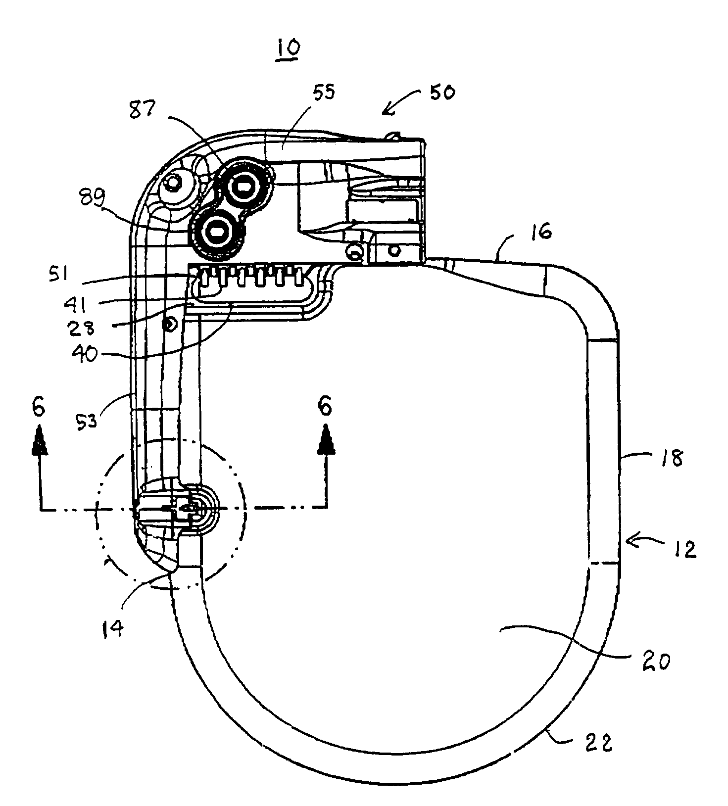
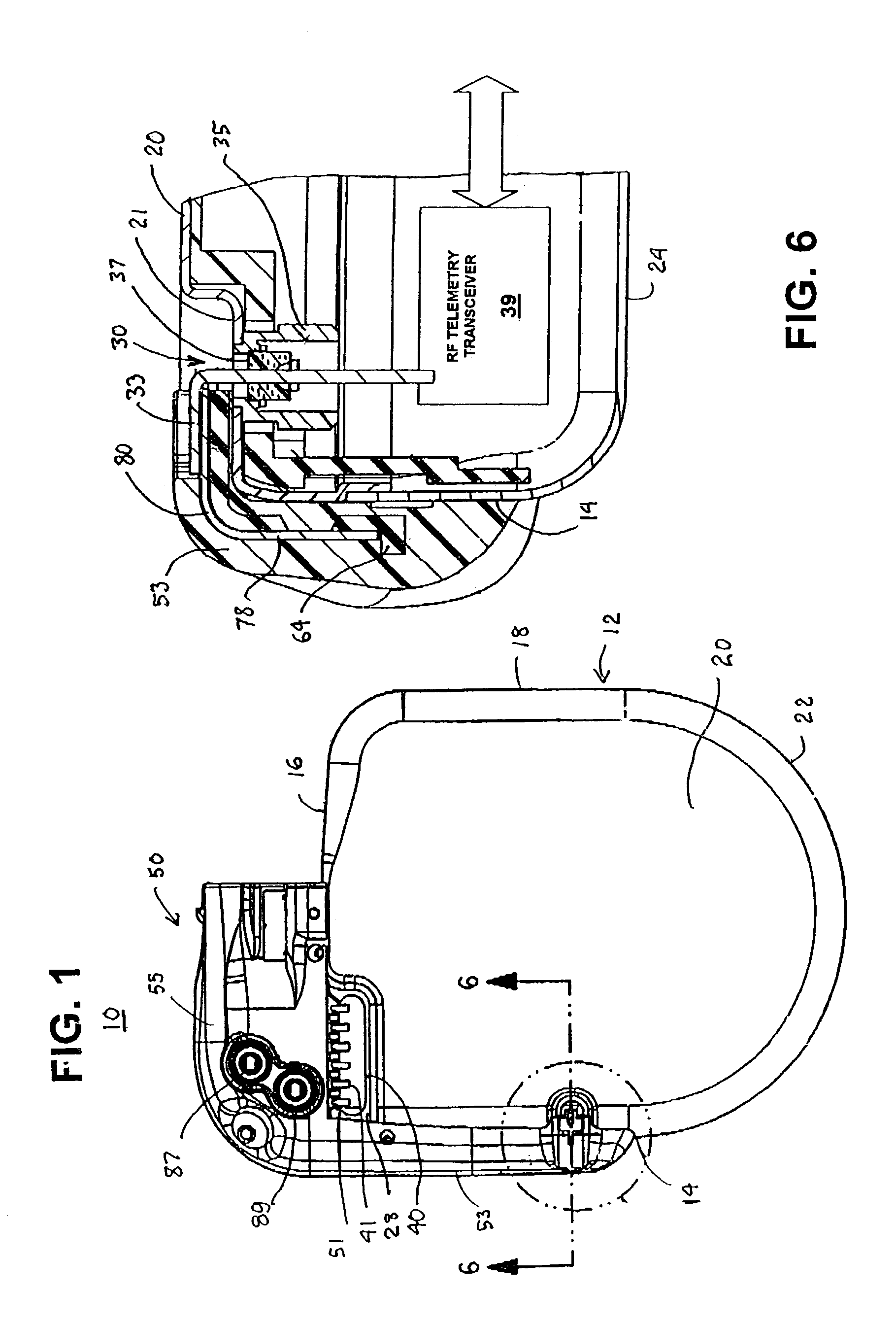
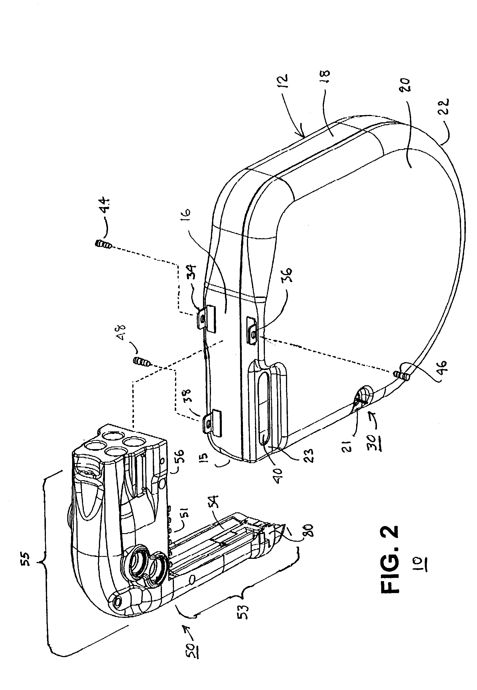
[0049]The present invention relates to providing an improved RF telemetry antenna disposed outside a hermetically sealed housing of any of the IMDs of the types described above. The following description is directed to various preferred embodiments of the invention implemented in the context of an ICD IPG. However, those of skill in the art will be readily able to adapt the teachings found herein to the other IMDs listed above and others to be devised that may or may not include connector components for connecting with electrical medical leads.

[0050]In accordance with the present invention, an elongated IMD telemetry antenna is supported outside the hermetically sealed housing of an IMD by an IMD connector header that is formed to extend in first and second orthogonal directions along adjoining minor sides of the IMD housing. The IMD telemetry antenna has two primary functions: to convert the electromagnetic power of a DT transmission of an EMD telemetry antenna propagated through t...


PUM


Abstract

Improved telemetry antennas and methods of fabrication for an implantable medical device (IMD) for use in uplink telemetry (UT) and downlink telemetry (DT) transmissions between the IMD and an external medical device (EMD) are disclosed. A first telemetry antenna element is supported to extend in a first direction along a minor side of the IMD housing by a first header segment, and a second antenna element is supported to extend in a second direction along a second minor side of the IMD housing by a second header segment. The first and second antenna elements are supported to extend apart at substantially 90° to one another, i.e., substantially orthogonally, in substantially a common plane to optimize UT transmission and DT reception of UHF telemetry signals by at least one of the first and second antenna elements depending upon the mutual spatial orientation with the antenna elements of an EMD antenna.

Description

FIELD OF THE INVENTION[0001]The present invention relates generally to an improved telemetry antenna and methods of fabrication for an implantable medical device (IMD) for use in uplink and downlink telemetry transmissions between the IMD and an external medical device.BACKGROUND OF THE INVENTION[0002]At present, a wide variety of IMDs are commercially released or proposed for clinical implantation. Such IMDs include implantable cardiac pacemakers as well as implantable cardioverter / defibrillators (ICDs) providing automatic cardioversion / defibrillation, anti-tachycardia pacing and bradycardia pacing functions of one or more heart chamber, drug delivery pumps, cardiomyostimulators, cardiac and other physiologic monitors, nerve, muscle, and muscle stimulators, e.g., sacral and spinal nerve stimulators and deep brain stimulators, cochlear implants, artificial hearts, etc.[0003]The cardiac pacemakers, ICDs, and the various tissue, organ and nerve stimulators typically comprise an implan...

Claims


Application Information

Patent Timeline
Patent Type & Authority Patents(United States)
IPC IPC(8): A61N1/365A61N1/372A61N1/375
CPCA61N1/375A61N1/37229A61N1/37512
Inventor DUBLIN, GARRY L.VERHOEF, WILLIAM D.WALLACE, RODNEY S.TWETAN, LEN D.KUSCHNIR, EUGENEHAUBRICH, GREGORY J.PRZYBYSZEWSKI, PIOTR JKRONICH, CHRISTINE G.DOUGHERTY, LEGAL REPRESENTATIVE, BONNIEVILLASECA, DECEASED, EDUARDO H.
Owner MEDTRONIC INC
Why Eureka
Try Eureka