Sequential test pattern generation using clock-control design for testability structures

a clock-control design and sequential circuit technology, applied in the direction of generating/distributing signals, pulse techniques, instruments, etc., can solve the problems of poor fault coverage results, high computational cost, and high overhead of automatic test pattern generation (atpg) for sequential circuits, so as to achieve no delay penalties and small overhead area

Inactive Publication Date: 2006-03-21
BELL SEMICON LLC
View PDF11 Cites 15 Cited by
  • Summary
  • Abstract
  • Description
  • Claims
  • Application Information

AI Technical Summary

Benefits of technology

[0009]In accordance with another aspect of the invention, each of the levels of registers may have multiple groups of registers associated therewith, with each of the groups being subject to clocking by one of the partitioned clock signals through the operation of group selection circuitry. The DFT structure in this case may include level selection circuitry and group selection circuitry, with the level selection circuitry configured for selecting a particular one of the levels for receiving a corresponding one of the clock signals, and the group selection circuitry configured for selecting a particular group of registers within a given one of the levels for receiving a corresponding one of the clock signals. The group selection circuitry thus allows further partitioning of the registers of the circuit within a given level. The group selection circuitry of the DFT structure may be implemented using G additional primary inputs of the circuit, where G is the maximum number of groups at any level, or by using a plurality of additional registers EGij, each of the registers EGij storing an enable value for a corresponding group j at level i.
[0011]Advantageously, the test pattern generation process of the present invention addresses the above-described problems associated with conventional testing of sequential circuits without requiring a scan-type DFT approach that significantly changes the circuit configuration in test mode. The DFT structures utilized in the illustrative embodiments introduce no delay penalties and only a small area overhead, and are compatible with at-speed testing.

Problems solved by technology

Automatic test pattern generation (ATPG) for sequential circuits is an extremely expensive computational process.
ATPG algorithms working on complex sequential circuits can spend many hours of central processing unit (CPU) time and still obtain poor results in terms of fault coverage.
There are a number of factors that contribute to the difficulty of the ATPG process for sequential circuits.
In addition, an ATPG algorithm may waste a substantial amount of time trying to justify illegal states.
Furthermore, an ATPG algorithm typically must complete an exhaustive search for each target fault that is to be identified as untestable.
Another difficulty is controlling and observing so-called “buried” FFs of the sequential circuit.
However, scan-type DFT techniques introduce delay penalties that result in performance degradation, and substantially increase circuit area overhead thereby increasing power consumption and decreasing yield.
In addition, scan-type DFT techniques are not directly compatible with at-speed testing.

Method used


Image

  • Sequential test pattern generation using clock-control design for testability structures
  • Sequential test pattern generation using clock-control design for testability structures
  • Sequential test pattern generation using clock-control design for testability structures

Examples


Embodiment Construction

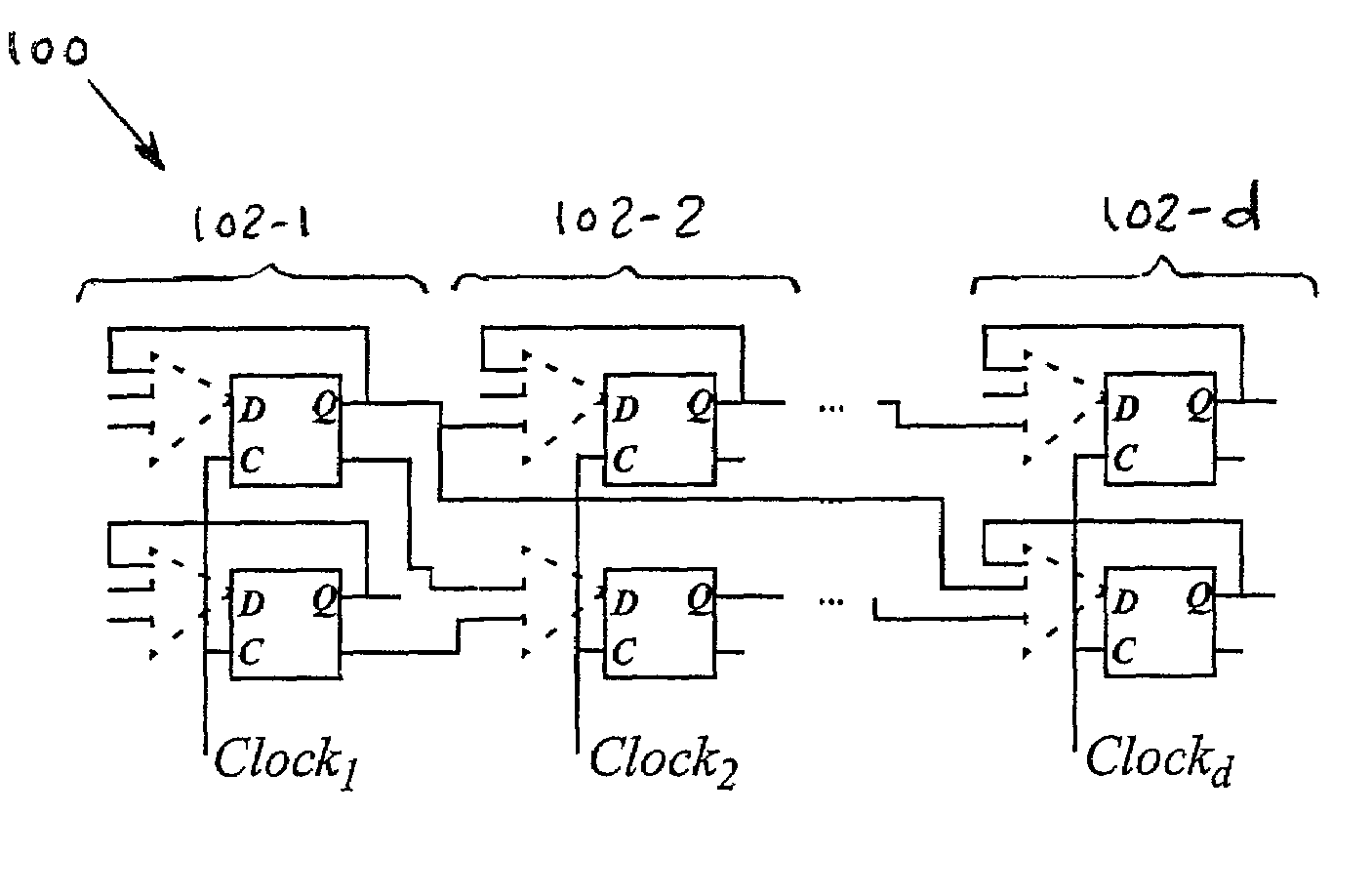
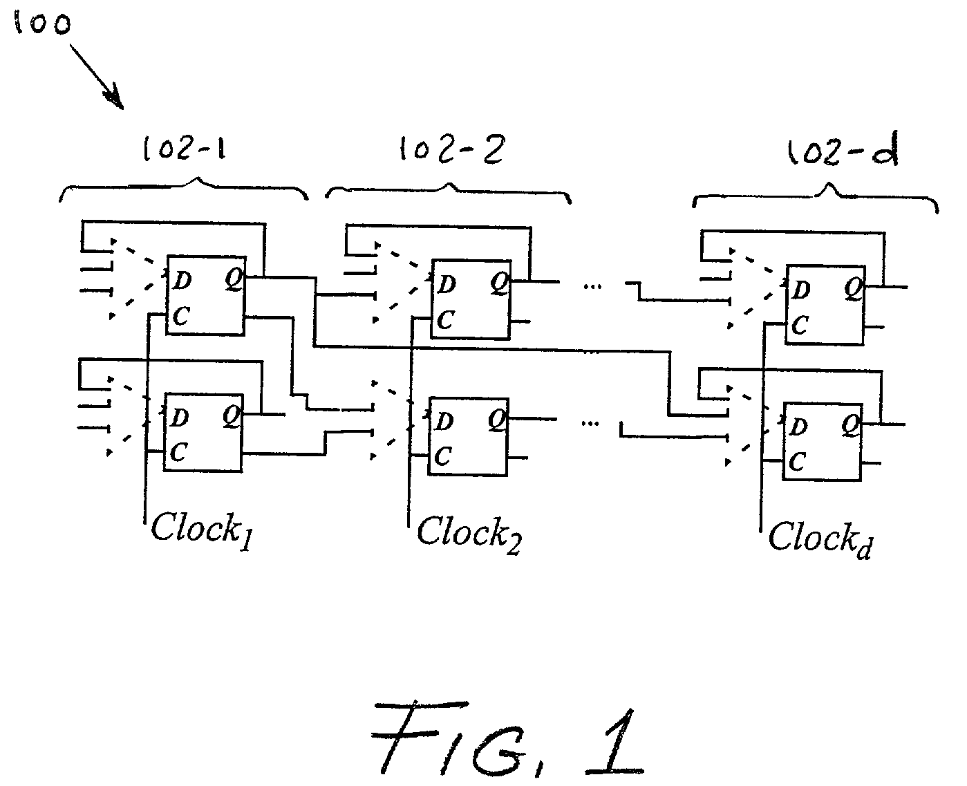
[0026]The present invention will be illustrated herein using exemplary sequential circuits. It should be understood, however, that the techniques of the invention can be applied to any desired type of sequential circuit. The term “register” as used herein is intended to include any arrangement of one or more flip-flops (FFs) or other circuit storage elements. The term “freezing” as used herein in conjunction with a clock signal refers to any technique for interrupting or otherwise stopping the clock signal.

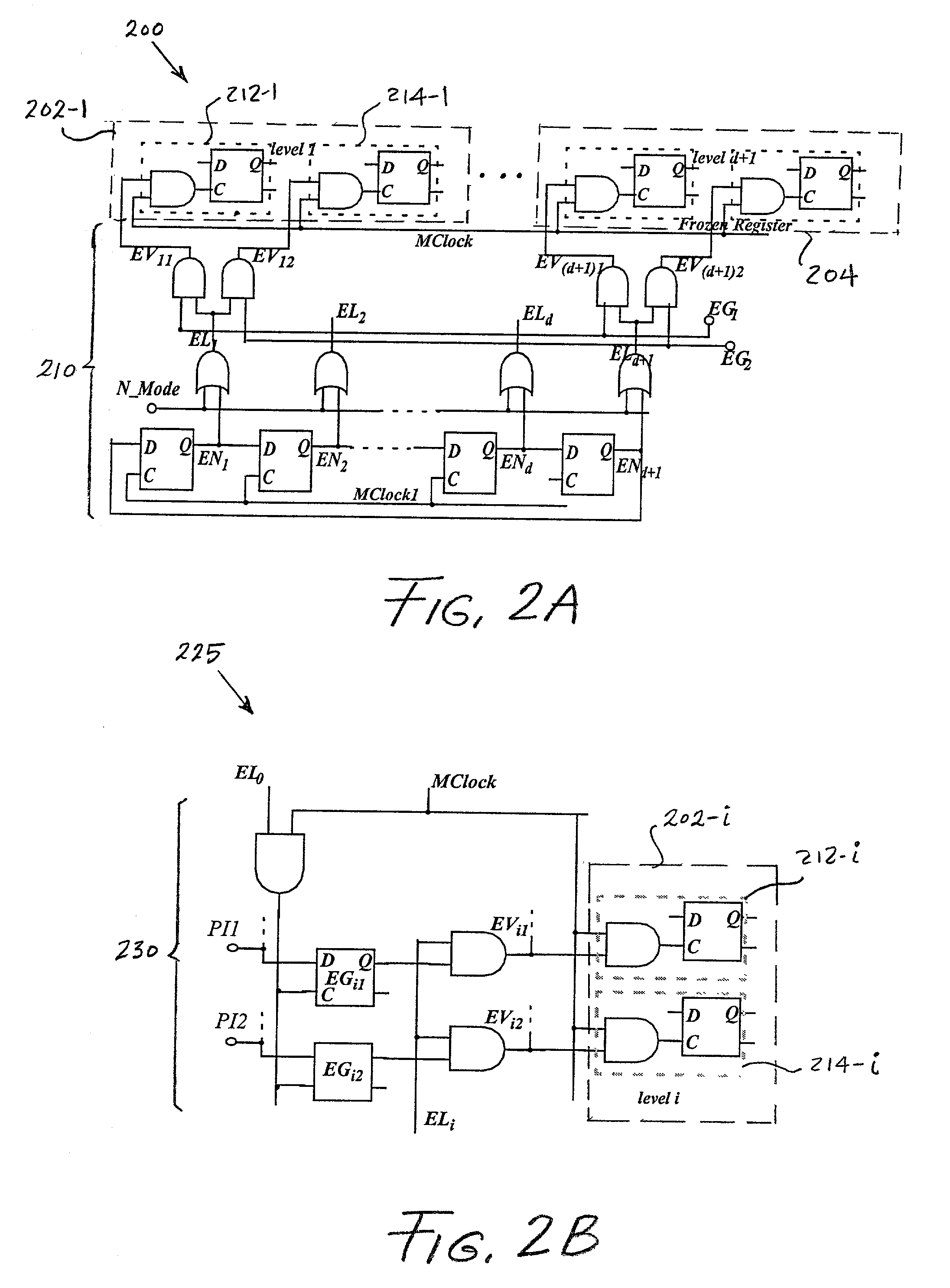
[0027]The present invention provides improved techniques for performing automatic test pattern generation (ATPG) that are particularly well-suited for use with sequential circuits. More particularly, the invention in the illustrative embodiments to be described provides improved design for testability (DFT) structures and a corresponding ATPG process. Advantageously, the DFT structures of the present invention do not introduce any significant delay penalty, have a very small area ...


PUM


Abstract

Techniques for testing a sequential circuit comprising a plurality of flip-flops or other types of registers. The circuit is first configured such that substantially all feedback loops associated with the registers, other than one or more self-loops each associated with a corresponding one of the registers, are broken. Test patterns are then generated for application to the circuit. The test patterns are applied to the circuit in conjunction with partitioned clock signals each of which is associated with a corresponding level of the circuit containing at least one of the self-loops.

Description

FIELD OF THE INVENTION[0001]The present invention relates generally to the design and testing of integrated circuits and other complex electronic circuits, and more particularly to techniques for generating test patterns for use in testing such circuits.BACKGROUND OF THE INVENTION[0002]Automatic test pattern generation (ATPG) for sequential circuits is an extremely expensive computational process. ATPG algorithms working on complex sequential circuits can spend many hours of central processing unit (CPU) time and still obtain poor results in terms of fault coverage. There are a number of factors that contribute to the difficulty of the ATPG process for sequential circuits. For example, it is generally necessary for an ATPG algorithm to use a model that includes an iterative array of time frames, where the number of time frames may be, in the worst case, an exponential function of the number of flip-flops (FFs) in the circuit. In addition, an ATPG algorithm may waste a substantial am...

Claims


Application Information

Patent Timeline
Patent Type & Authority Patents(United States)
IPC IPC(8): G06F11/00G01R31/28G01R31/3183G01R31/317G01R31/3185G06F1/04H03K19/00
CPCG01R31/318522G01R31/31704
Inventor ABRAMOVICI, MIRONYU, XIAOMING
Owner BELL SEMICON LLC
Why Eureka
Try Eureka