Restraint system for restraining a person in a vehicle of transportation

a technology for restraining and people, applied in the direction of seating furniture, sports equipment, garments, etc., can solve the problems of affecting the economic viability of the person, affecting the safety of the person,

Active Publication Date: 2006-03-28
SCHROTH SAFETY PRODS
View PDF10 Cites 33 Cited by
  • Summary
  • Abstract
  • Description
  • Claims
  • Application Information

AI Technical Summary

Benefits of technology

[0020]According to another feature of the present invention, the engagement structure can be so configured that a length of an engagement structure component on the shoulder belts is shorter than a length of an engagement structure component on the legs.
[0021]According to

Problems solved by technology

Oftentimes these injuries resulted in catastrophic outcomes such as paralysis or even death.
Although this situation can be improved through integration of airbags, such systems necessitate a modification of the compartment structure of the helicopter, the arrangement of complicated sensors and the provision of monitoring systems.
Costs and added weight thus render this approach economically unviable.
However, a drawback of the HANS system is the relative distance between the shoulder belts and the occupant's body as

Method used


Image

  • Restraint system for restraining a person in a vehicle of transportation
  • Restraint system for restraining a person in a vehicle of transportation
  • Restraint system for restraining a person in a vehicle of transportation

Examples


first embodiment

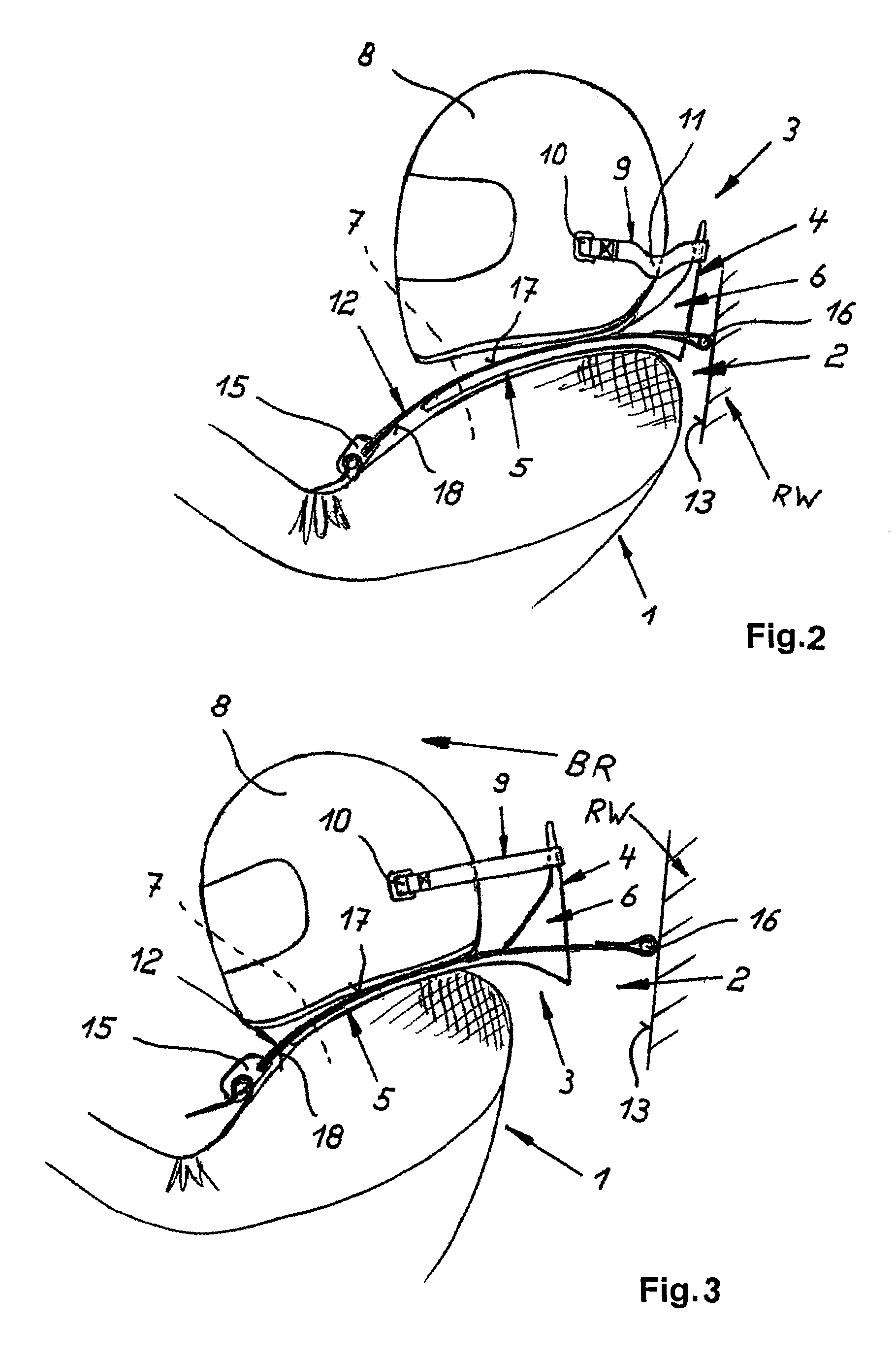
[0043]Turning now to FIG. 4, there is shown a cross sectional and perspective view of one of the shoulder belts 12 and one of the legs 5 of the shoulder yoke 4 in accordance with the novel and inventive head and neck support system 3. As both shoulder belts 12 and both legs 5 are of identical construction, it will be understood by persons skilled in the art that a description of one of the shoulder belts is equally applicable to the other shoulder belt, and a description of one of the legs is equally applicable to the other leg.

[0044]The leg 5 has a topside 17 which is formed with a channel-like depression 19. Cemented into the depression 19 is a shallow strip 20 which is made of rubber and formed with a central trough-shaped longitude groove 21. Molded onto a leg-confronting underside 18 of the shoulder belt 12 is a rounded longitude bead 22 which is made of plastic and has a cross section to conform to the cross section of the longitude groove 21. When the shoulder belt 12 is taut...

second embodiment

[0046]FIG. 5 shows a cross sectional and perspective view of a head and neck support system 3 according to the present invention. Parts corresponding with those in FIG. 4 are denoted by identical reference numerals and not explained again. The description below will center on the differences between the embodiments. In this embodiment, provision is made for a shallow strip 20a of rubber which is received in the depression 19 and provided with a central longitude bead 23 of omega-shaped cross section. Attached to the leg-confronting underside 18 of the shoulder belt 12 is a strip 24 made of plastic or rubber and having a triangular cross section which is at a greatest thickness in the vertical longitudinal center plane of the shoulder belt 12 and decreases in thickness in the direction of the marginal areas 25 of the shoulder belt 12. Formed in the strip 24 is a central through-shaped longitude groove 26 of U-shaped cross section.

[0047]When the shoulder belt 12 is taut over the leg 5...

third embodiment

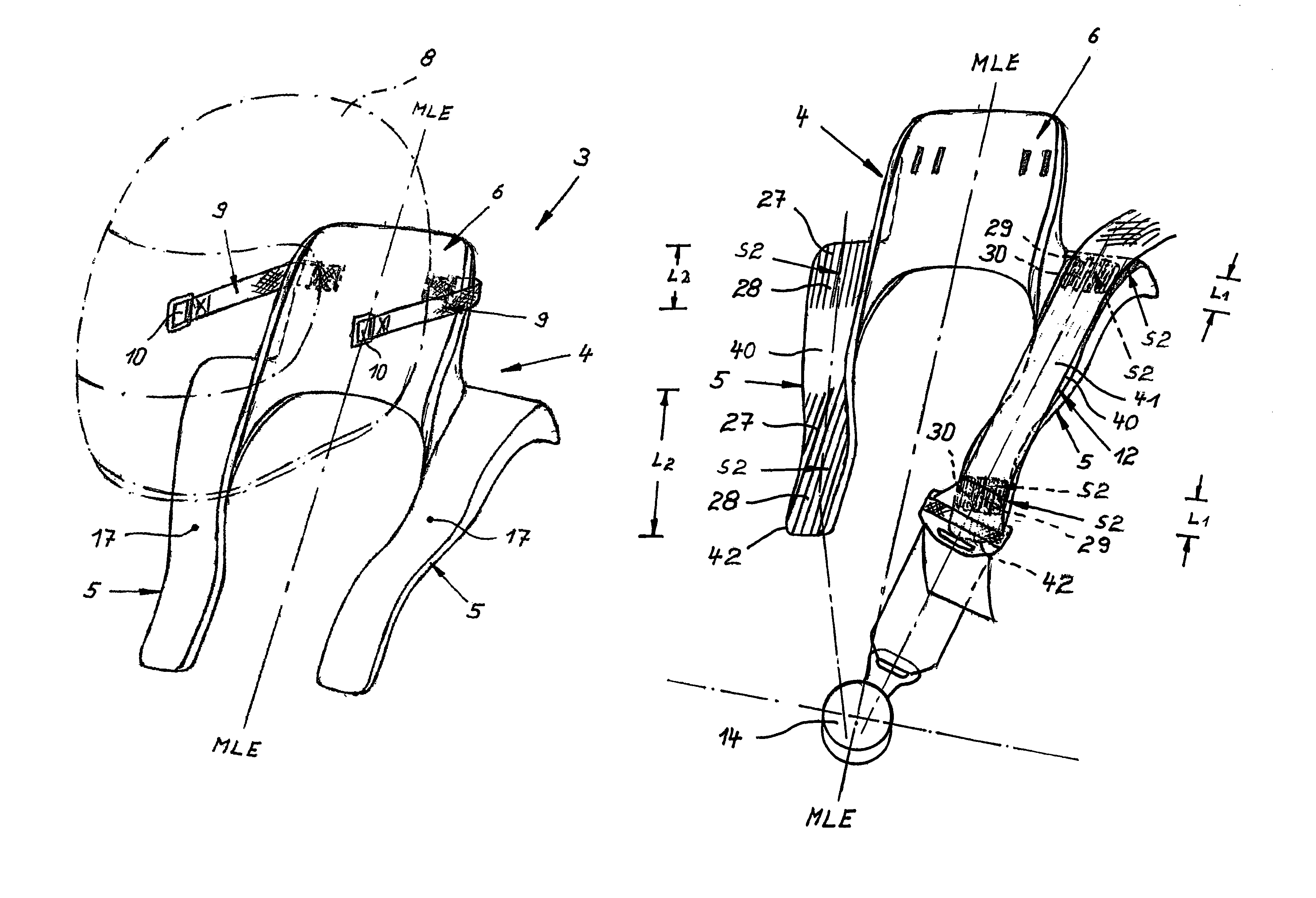
[0049]Turning now to FIG. 7, there is shown a cross sectional and perspective view of a head and neck support system 3 according to the present invention. Parts corresponding with those in FIG. 4 are denoted by identical reference numerals and not explained again. The description below will center on the differences between the embodiments. In this embodiment, provision is made for a shallow strip 20b of rubber which is received in the depression 19 and provided with several longitude beads 27 and longitude grooves 28 having a rounded or trough-shaped cross section and disposed in parallel side-by-side relationship. The leg-confronting underside 18 of the shoulder belt 12 is formed with longitude beads 29 and longitude grooves 30 with rounded or trough-shaped cross section to complement the cross section of the longitude beads 27 and longitude grooves 28 of the shallow strip 20b of the leg 5. The longitude beads 29 and longitude grooves 30 on the underside 18 of the shoulder belt 12...


PUM


Abstract

A restraint system for restraining a person in a vehicle of transportation, includes a safety harness having length adjustable shoulder belts and a buckle for connecting the shoulder belt on a chest-side of a person and a stiff U-shaped shoulder yoke having legs, which are contoured to a torso of the person, and a high collar interconnecting the legs, whereby the shoulder belts are secured by a fastening mechanism behind the collar. The legs of the shoulder yoke and the shoulder belts have confronting sides which are formed, at least partially, with an interacting engagement structure which is configured to increase friction as the shoulder belts move in relation to the legs in longitudinal direction, while inhibiting a displacement of the shoulder belts in relation to the legs in transverse direction.

Description

CROSS-REFERENCES TO RELATED APPLICATIONS[0001]This application claims the priority of German Patent Application, Serial No. 103 14 423.4, filed Mar. 28, 2003, pursuant to 35 U.S.C. 119(a)–(d), the disclosure of which is incorporated herein by reference.BACKGROUND OF THE INVENTION[0002]The present invention relates, in general, to a restraint system for restraining a person in a vehicle of transportation, and more particularly to an arrangement for positioning the shoulder belts of a safety harness in longitudinal direction of legs of a U-shaped shoulder yoke.[0003]Due to the ever increasing speeds in motor sport, especially formula racing, head and neck injuries become more and more common, when a racecar crashes against track barriers or in the event of a collision between two cars. Oftentimes these injuries resulted in catastrophic outcomes such as paralysis or even death. Therefore, head and neck restraining systems have been developed to prevent the head of a driver, in the even...

Claims


Application Information

Patent Timeline
IPC IPC(8): A42B1/06A42B3/04B60R21/00B60R22/00B60R22/02B60R22/12B60R22/18B60R22/28
CPCA42B3/0473B60R22/02B60R22/28B60R22/12B60R22/001B60R2022/285B60R2021/0086B60R2022/1818
Inventor SCHROTH, CARL-JURGEN
Owner SCHROTH SAFETY PRODS
Why Eureka
Try Eureka