High performance cable tie

a high-performance, cable technology, applied in the field of cable tie, can solve problems such as friction resistance, and achieve the effects of increasing frictional force, increasing resistive force, and increasing frictional for

Inactive Publication Date: 2006-03-28
THOMAS & BETTS INT INC
View PDF29 Cites 79 Cited by
  • Summary
  • Abstract
  • Description
  • Claims
  • Application Information

AI Technical Summary

Benefits of technology

[0009]The strap and pawl teeth each have planar portions which engage one another to obstruct retraction of the strap from the head. The longitudinal spacing of the strap and pawl teeth are equivalent providing for the engagement of multiple pairs of strap and pawl teeth to resist retraction of the strap from the head. This resistance to retraction of the strap from the head is thereby provided by an increased number of teeth thereby increasing the resistive force.
[0010]The surface of the pawl between the exit end of the passageway and the pawl tooth nearest thereto has a concave portion which engages the convex portion of the opposing strap tooth when the pawl pivots in response to retraction of the strap from the head. This engagement between the concave and convex portions forces the strap against the side of the passageway increasing the frictional force which resists sliding of the strap against the side of the passageway. This increased frictional force provides increased resistance to retraction of the strap from the head since such retraction normally entails sliding of the strap against the side of the passageway.
[0011]The pivoting of the pawl resulting from retraction of the strap from the head is limited by a heel which engages an inner surface of the head. This engagement of the heel maintains the pivoting of the pawl within the range of angular displacement typically provided by the flexibility of materials normally used for cable ties.

Problems solved by technology

Such sliding contact results in frictional resistance to such insertion of the strap through the passageway.

Method used


Image

  • High performance cable tie
  • High performance cable tie
  • High performance cable tie

Examples


Embodiment Construction

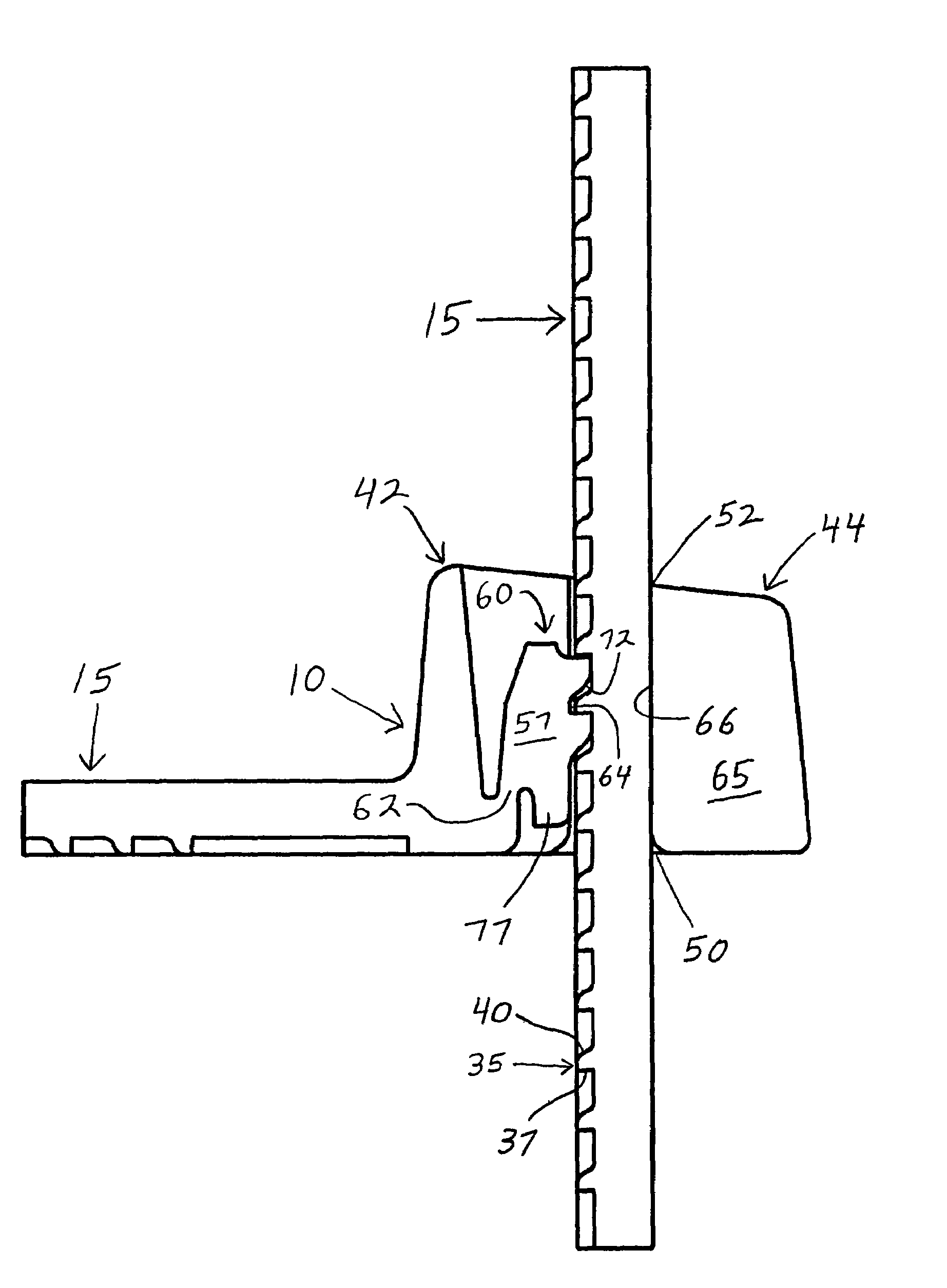
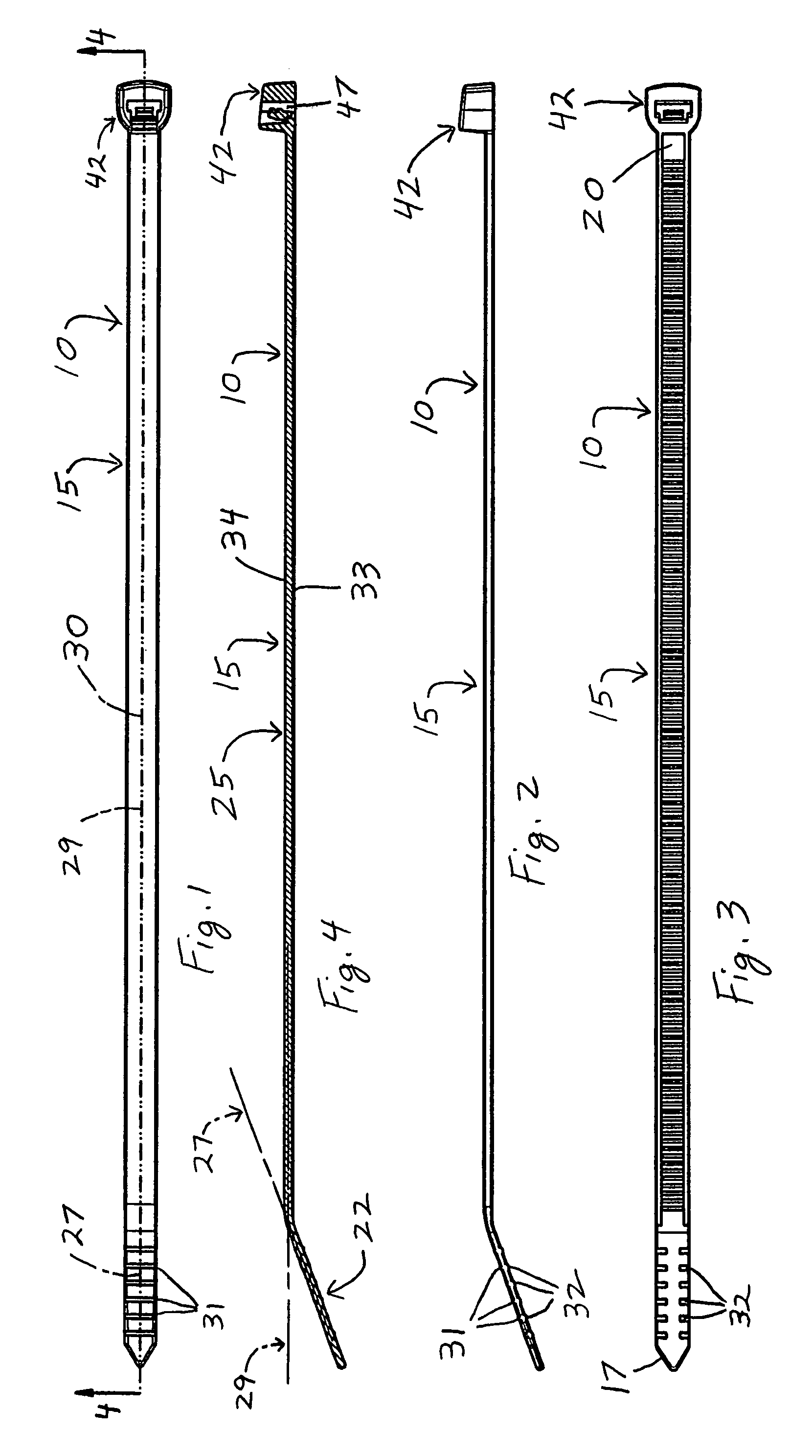
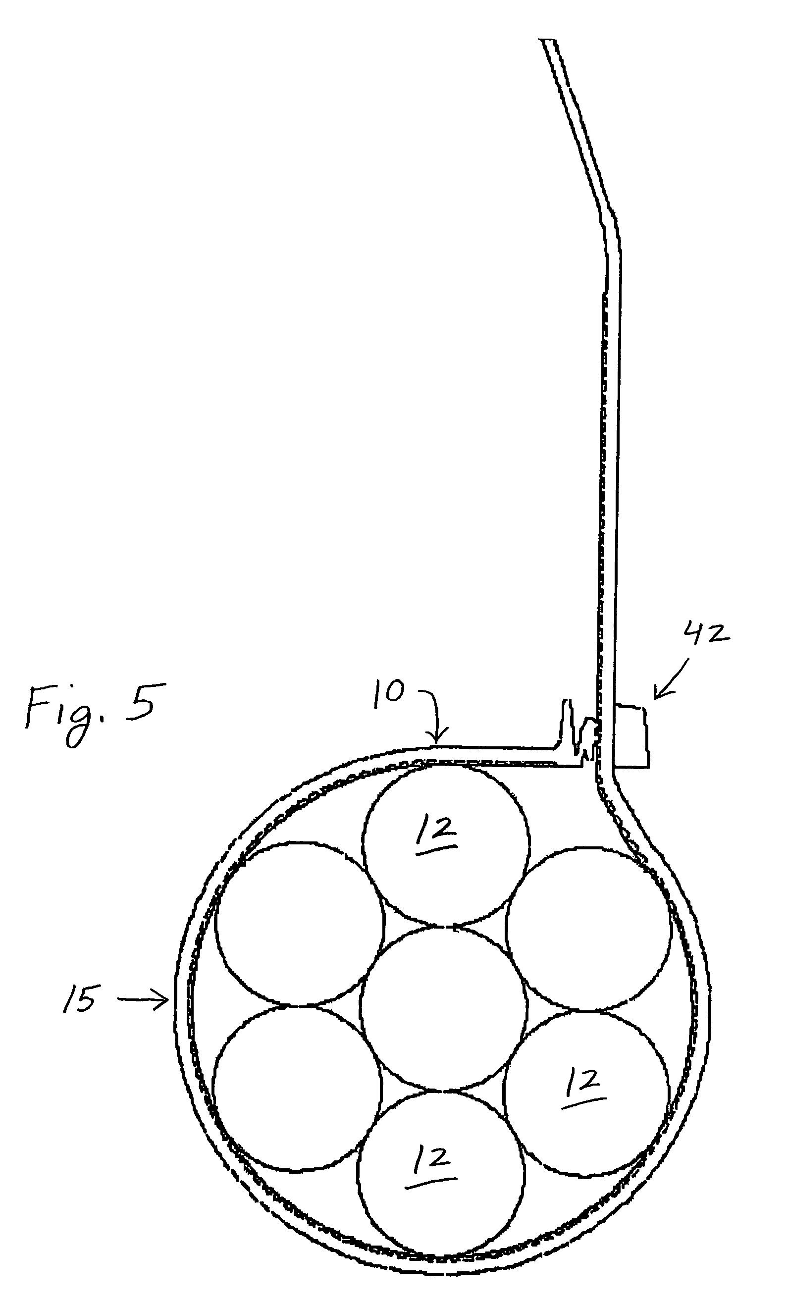
[0024]Referring to the drawings and more particularly to FIGS. 1 to 5, a high performance cable tie 10 is shown for bundling a collection of elongate articles 12, such as wires or cables.

[0025]The cable tie 10 includes an elongate strap 15 having opposing free and base ends 17, 20. The strap 15 has a tail portion 22 which is contiguous with the free end 17, and a toothed portion 25 which is contiguous with the base end 20. The tail and toothed portions 22, 25 have respective longitudinal central axes 27, 29 and are oriented such that the axes 27, 29 are contained in a central plane 30. The toothed portion 25, and in a possible embodiment the tail portion 22, is deformable transversely such that the respective axes 27, 29 are contained in the central plane 30. When the strap 15 is not deformed, the respective central axes 27, 29 of the tail and toothed portions 22, 25 are inclined relative to one another, as shown in FIGS. 2 and 4.

[0026]The tail portion 22 has, on opposing surfaces t...


PUM


Abstract

A high performance cable tie includes an elongate strap, and a head extending from one end of the strap. The strap and pawl teeth each have convex portions which engage one another during insertion of the strap through the head. The strap and pawl teeth also each have planar portions which engage one another to obstruct retraction of the strap from the head. The longitudinal spacing of the strap and pawl teeth are equivalent. The surface of the pawl between the exit end of the passageway and the pawl tooth nearest thereto has a concave portion which engages the convex portion of the opposing strap tooth when the pawl pivots in response to retraction of the strap from the head. This pivoting of the pawl is limited by a heel which engages an inner surface of the head.

Description

BACKGROUND OF THE INVENTION[0001]The present invention relates generally to a cable tie, and more specifically, to a cable tie having a strap and a head which cooperate to facilitate insertion of the strap into the head and retention therein of the strap.[0002]Cable ties are used to bundle or secure a group of articles such as electrical wires or cables. Cable ties of conventional construction include a cable tie head and an elongate strap extending therefrom. The strap is wrapped around a bundle of articles and thereafter inserted through a passageway in the head. The head of the cable tie typically supports a locking element which extends into the passageway allowing the strap to be inserted through the passageway but preventing retraction of the strap therethrough. Two longitudinally separated portions of the strap are thereby secured to the head to form a portion of the strap into a loop for bundling together the group of articles.[0003]In use, the installer manually places the ...

Claims


Application Information

Patent Timeline
Patent Type & Authority Patents(United States)
IPC IPC(8): B65D63/10F16L3/233B65D63/12
CPCF16L3/2334Y10T24/1498
Inventor MAGNO, JR., JOEY D.CAI, XUEMING
Owner THOMAS & BETTS INT INC
Why Eureka
Try Eureka