
Fiber blowing and heat dissipating system of single-sided circular knitting machine

a technology of fiber blowing and heat dissipation system, which is applied in the direction of knitting, textiles and papermaking, etc., can solve the problems of shortening the life of the circular knitting machine, affecting the quality of cloth, and causing defects, so as to stabilize the smoothness of knitting operation and reduce the temperature of the heat

Inactive Publication Date: 2006-03-28
PAI LUNG MACHINERY MILL CO LTD
View PDF12 Cites 38 Cited by
  • Summary
  • Abstract
  • Description
  • Claims
  • Application Information

AI Technical Summary

Benefits of technology

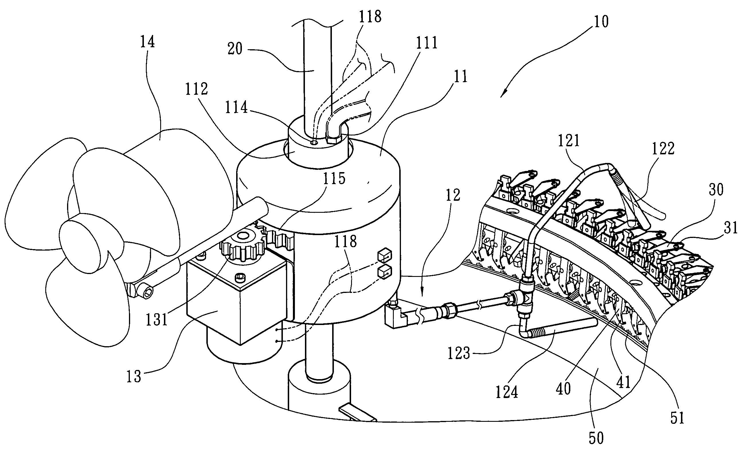
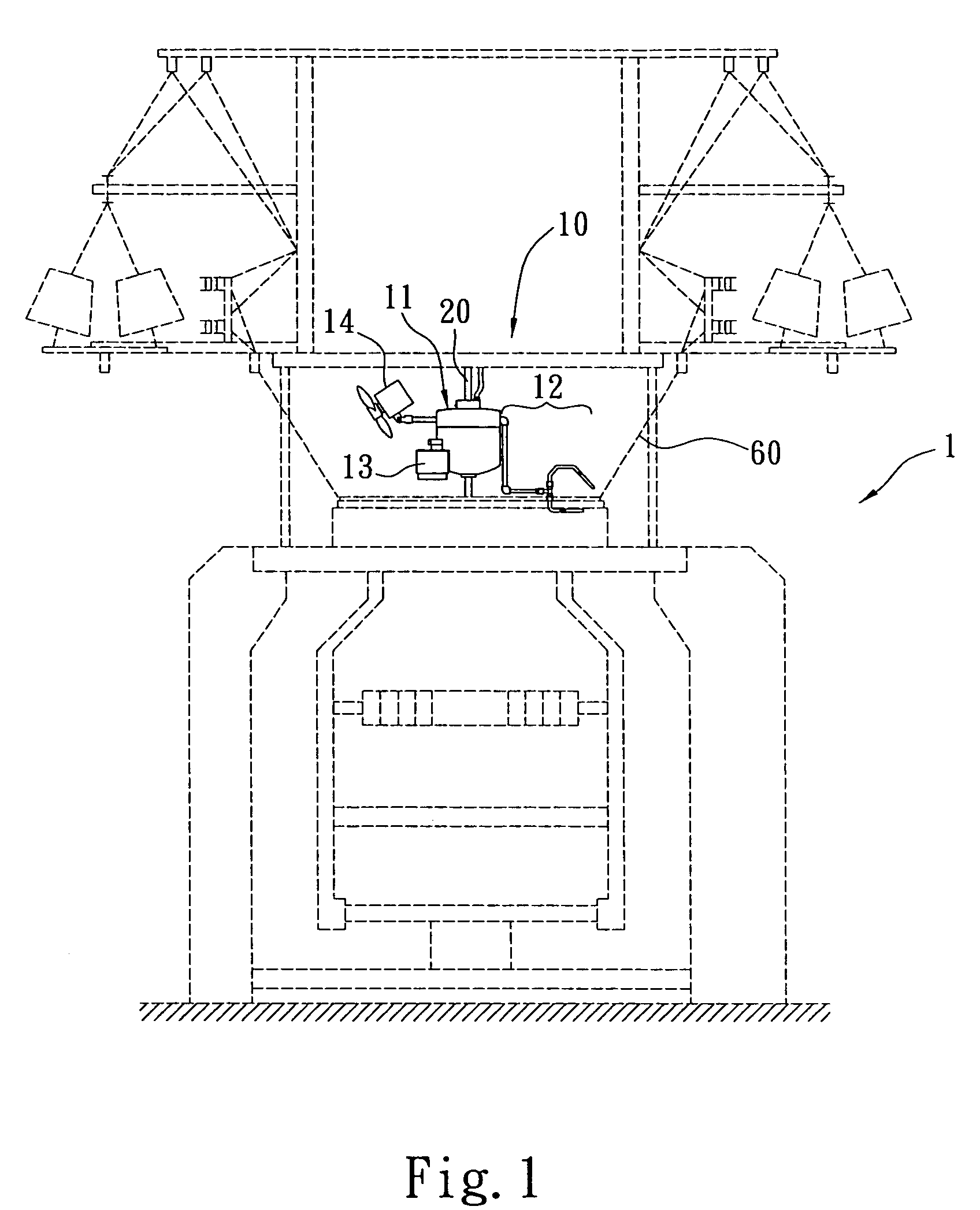
[0005]The primary objective of the present invention is to provide a fiber blowing and heat dissipating system of single-sided circular knitting machine that centralizes an airflow to blow cotton fibers away from a yarn passing eyelet of a yarn passing plate, a yarn feeding eyelet of yarn feeding nozzle, and a knitting needle of the circular knitting machine and to lower the temperature of the heat produced by the friction between the rotation of a needle cylinder and the knitting needle, and thus the invention can stabilize the smoothness of the knitting operation, maintain the life of the circular knitting machine, and assures the quality of knitting products.
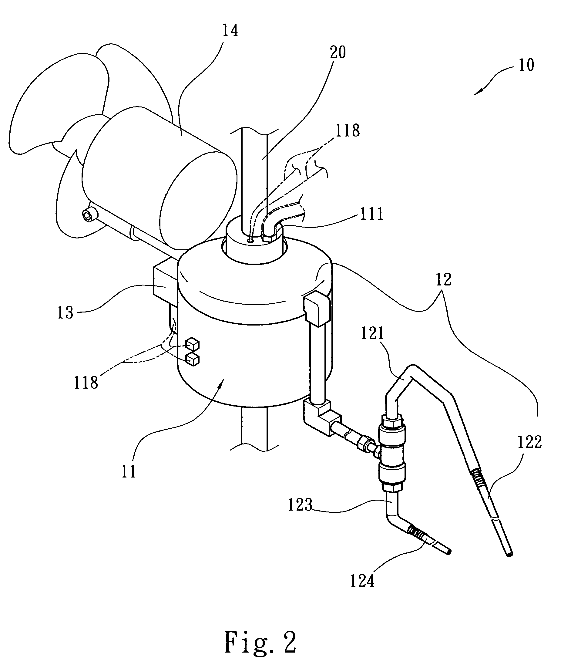
[0007]Thereby, the soft tube is extended to a position proximate to the yarn passing plate to freely sway and blow air, and the second fiber blowing pipe is extended to a position proximate to the yarn feeding nozzle and the knitting needle to blow air, and being capable of centralizing an airflow to effectively blow away cotton fibers and dissipating heat for the yarn passing plate, the yarn feeding nozzle, and the knitting needle.

Problems solved by technology

If these cotton fibers are not removed, each component of the circular knitting machine will get stuck easily, and that will affect the smoothness of the knitting operation and shorten the life of the circular knitting machine.
Furthermore, defects will be produced if the cotton fibers and the cotton yarns are knitted together to produce a piece of cloth, and that will affect the quality of the cloth.

Method used


Image

  • Fiber blowing and heat dissipating system of single-sided circular knitting machine
  • Fiber blowing and heat dissipating system of single-sided circular knitting machine
  • Fiber blowing and heat dissipating system of single-sided circular knitting machine

Examples


Embodiment Construction

[0017]The technical contents of the present invention will now be described in more detail hereinafter with reference to the accompanying drawings that show various embodiments of the invention.

[0018]Refer to FIGS. 1, 2, 3 and 6 respectively for the schematic view, the perspective view, the cross-sectional view, and the preferred embodiment of a fiber blowing and heat dissipating system of single-sided circular knitting machine according to the present invention. The present invention is particularly suitable for being used for a single-sided circular knitting machine 1. The single-sided circular knitting machine 1 comprises a plurality of yarn passing plates 30 for connecting cotton yarn 60, a plurality of yarn feeding nozzles 40, and a plurality of knitting needles 51 for knitting the cotton yarn 60, wherein the cotton yarn 60 is passed separately through yarn passing eyelets 31 of the yarn passing plates 30 and a yarn feeding eyelets 41 of the yarn feeding nozzles 40.

[0019]The fi...


PUM


Abstract

A fiber blowing and heat dissipating system of single-sided circular knitting machine includes a fixed rod, a revolving supply device, and a fiber blowing device, wherein the revolving supply device includes a fixed rod, a rotary air supply section, and a driving motor. The fixed axle has an air inlet at its top, and the rotary air supply section has an air passage interconnected with the air inlet and connected to the fiber blowing device, such that the driving motor is driven to rotate around the fixed axle to centralize the air flow to blow away the cotton fibers easily produced at a yarn passing eyelet of the yarn passing plate and the yarn feeding eyelet of a yarn feeding nozzle and a knitting needle. The invention also can lower the heat produced by the friction between the rotation of the needle cylinder and the knitting needle.

Description

FIELD OF THE INVENTION[0001]The present invention relates to a fiber blowing and heat dissipating system, and more particularly to a fiber blowing and heat dissipating system applicable to a circular knitting machine for knitting single-sided knitted cloth.BACKGROUND OF THE INVENTION[0002]To improve the smoothness of the knitting operation during a knitting process of a circular knitting machine, the cotton yarn must be tightly pulled, and the cotton yarns usually produce cotton fibers in the process of inputting, guiding, and feeding the cotton yarns. If these cotton fibers are not removed, each component of the circular knitting machine will get stuck easily, and that will affect the smoothness of the knitting operation and shorten the life of the circular knitting machine. Furthermore, defects will be produced if the cotton fibers and the cotton yarns are knitted together to produce a piece of cloth, and that will affect the quality of the cloth.[0003]In view of the foregoing pro...

Claims


Application Information

Patent Timeline
IPC IPC(8): D04B35/32
CPCD04B35/32D04B35/30
Inventor CHEN, SHIH-LUNG
Owner PAI LUNG MACHINERY MILL CO LTD
Learn More