Continuous wave ultrasonic process monitor for polymer processing

a technology of ultrasonic process monitor and polymer processing, which is applied in the direction of vibration measurement in solids, heat measurement, lubrication elements, etc., can solve the problems of high equipment cost, sensitive equipment, and difficulty in sensing these variables

Inactive Publication Date: 2006-03-28
UNIV OF UTAH RES FOUND
View PDF24 Cites 27 Cited by
  • Summary
  • Abstract
  • Description
  • Claims
  • Application Information

AI Technical Summary

Problems solved by technology

While the plastic variables have been shown to be important, sensing these variables has been difficult due to the invasive nature of existing sensing techniques.
Three common problems in using ultrasonic sensing techniques have been the high cost of the required equipment, the delicate nature of the equipment, and the level of understanding required to operate the equipment.
The drawback to each of these techniques is primarily the invasive nature of the measurement.
Direct cavity pressure measurement requires a hole cut into the mold cavity, which results in a noticeable mark on the molded product.
In situations where this is unacceptable, such as automotive lighting lenses, optical disks, et cetera, the sensor cannot be used.
The common melt temperature sensing techniques often require a probe extended into the melt and have difficulty in defining the sensed volume reliably.
While the ultrasound techniques show promise, the equipment typically required in such systems is very expensive, very delicate, and quite complex to operate.

Method used


Image

  • Continuous wave ultrasonic process monitor for polymer processing
  • Continuous wave ultrasonic process monitor for polymer processing
  • Continuous wave ultrasonic process monitor for polymer processing

Examples


Embodiment Construction

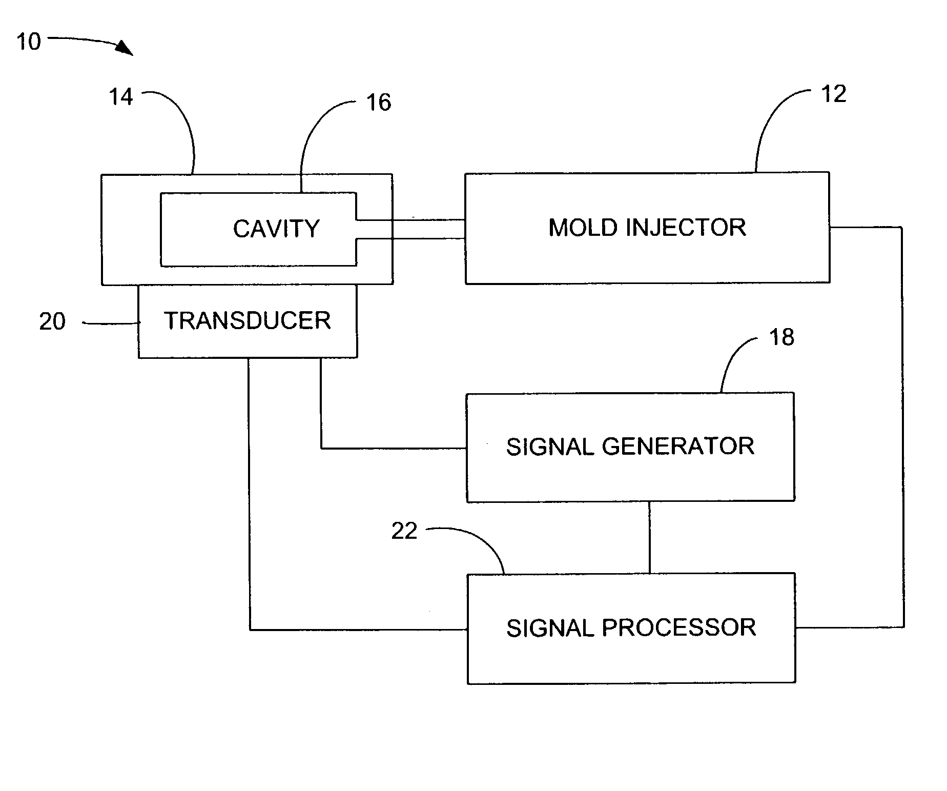
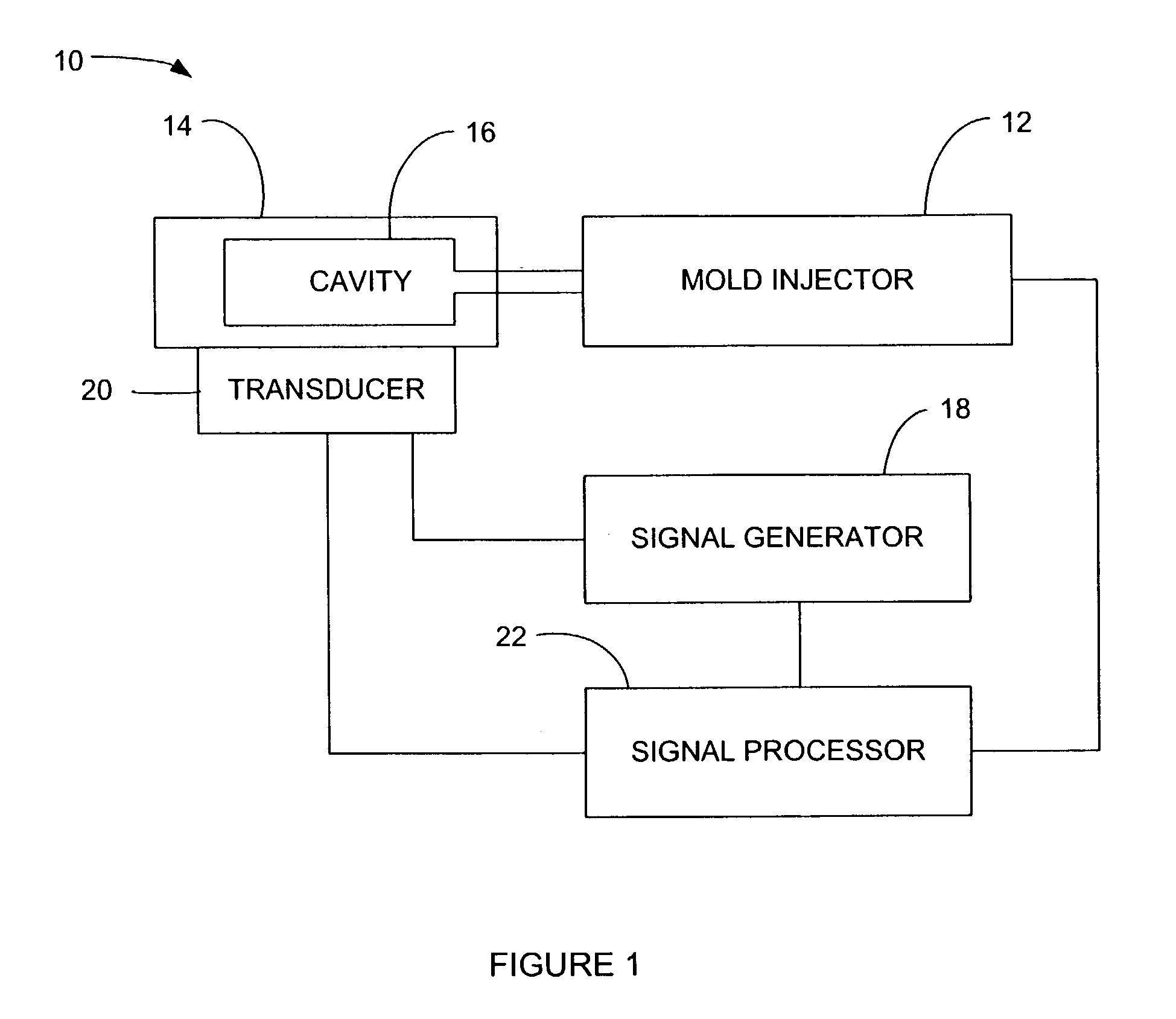
[0024]The present invention introduces continuous wave ultrasound monitoring techniques that typically utilize a piezoelectric crystal to generate and detect ultrasonic energy applied to a test item. When the piezoelectric crystal is excited by an imposed electric voltage, the crystal changes shape, which produces a vibration. The vibration propagates through the thickness of the object to which it is attached, generating reflections at selected interfaces, such as between the crystal, the object, and any other layer touching approximate on another. The magnitude of the reflections is a function of the mismatch in material properties between the two interfacing materials. The reflected energy propagates back to the crystal, causing the crystal to vibrate, which then produces an alternating voltage. As suggested by the name continuous wave ultrasound, the crystal utilized in such a system vibrates continuously using a sine wave or other periodic waveform. This is in contrast to a con...


PUM

PropertyMeasurementUnit
acoustic energyaaaaaaaaaa
resonant frequencyaaaaaaaaaa
acoustic energy frequencyaaaaaaaaaa

Abstract

An injection molding apparatus is disclosed that includes an injection mold, a mold injector, and means for monitoring the injection mold process using acoustic energy. The injection mold includes a cavity for receiving an injection mold material, such as a polymer as injected via the mold injector. The monitoring system includes an acoustic energy generator, an ultrasonic crystal, and an energy monitoring device. The acoustic energy generator produces continuous acoustic energy to be non-invasively applied to the injection mold as the polymer is delivered into the mold. The energy monitoring device monitors changes in dynamic parameters of a resulting continuous resonant frequency established by the acoustic energy generator through the ultrasonic crystal. The ultrasonic crystal serves also as a transducer to receive an output signal from the mold to be delivered to the energy monitoring device. It is this output signal that is processed to determine dynamic parameters that change based on the change of the continuous resonant frequency. This change of dynamic parameters can identify at least one characteristic of the polymer such that refined control of the injection process may be achieved by monitoring such characteristics through the continuous wave resonant frequency monitoring approach applied by the monitoring system.

Description

[0001]This application claims the benefit U.S. Provisional Application No. 60 / 373,963, filed Apr. 18, 2002, and entitled “Continuous Wave Ultrasonic Process Monitor for Polymer Processing.”BACKGROUND OF THE INVENTION[0002]1. Field of the Invention[0003]The present invention relates generally to monitoring systems for use in process manufacturing apparatus and, more specifically, the present invention relates to cavity based ultrasonic resonance monitoring in plastic molding processes and an apparatus for performing the same.[0004]2. Background of the Art[0005]Modern injection molding practice requires the measurement of “plastic” variables such as melt temperature and cavity pressure in order to produce the highest quality polymer parts. While the plastic variables have been shown to be important, sensing these variables has been difficult due to the invasive nature of existing sensing techniques. Three common problems in using ultrasonic sensing techniques have been the high cost o...

Claims


Application Information

Patent Timeline
Patent Type & Authority Patents(United States)
IPC IPC(8): G01B17/00B29CB29C45/00B29C45/76B29C45/77B29C45/78G01K7/32G01N29/00
CPCB29C45/76B29C45/77G01K7/32B29C45/78B29C2945/76471B29C2945/76474
Inventor THOMAS, CHARLES L.EDWARDS, RUSSELLDIAO, LIYONG
Owner UNIV OF UTAH RES FOUND
Why Eureka
Try Eureka