Method and apparatus for plasma optimization in water processing

a technology of optimizing methods and equipment, applied in the direction of coatings, chemical vapor deposition coatings, electric discharge tubes, etc., can solve the problems of reducing device yield or requiring extensive further processing to remove damage, affecting the efficiency of device manufacturing, etc., to achieve optimal wafer processing, reduce the size of the device, and facilitate the effect of control

Inactive Publication Date: 2006-03-28
NOVELLUS SYSTEMS
View PDF19 Cites 426 Cited by
  • Summary
  • Abstract
  • Description
  • Claims
  • Application Information

AI Technical Summary

Benefits of technology

[0016]The advantages of the present invention are numerous. Most notably, through use of strategic gas injection to certain locations within the plasma optimization apparatus, specific plasma species may be generated in a controlled and optimal manner. The type of reactive species formed with the gas injection of the present invention may easily be controlled by controlling the ionic content of the plasma effluent prior to injection of the gas. In addition, because of the structures of the plasma optimization structure of the present invention, even more control plasma management may be utilized. Depending on the location of the gas injection as well as by varying the size of gas injection nozzles or by incorporating a manifold injection apparatus within the baffles, the present invention may control input of gases at various stages of plasma reactivity. As a result, the present invention enables usage of specific types of plasma effluent for optimal wafer processing.
[0017]In addition, the present invention has an ability to recombine ions and the use in a closed coupled plasma source where the plasma is not distantly remote from the injection port and reactor. The present invention enables downstream addition of reactant gases in a close coupled downstream plasma source. In addition, the prior art apparatus is extremely large, but the size of downstream optimization structure of the present invention may have a significantly smaller size and the ionic content can be controlled by either the location of the injection port or the size of the orifice or both as well as a simplified means of temperature control.

Problems solved by technology

Subsequent heating of the wafer can produce wafer temperatures high enough to produce thermal damage to critical structures on the wafer, or detrimentally impacting the process, thus reducing device yield or requiring extensive further processing to remove the damage.
The presence of electrons and ions that remain in the effluent gases which interact with the wafer surface can activate a mobile charge (Qm) on the surface of the wafer or induce damage to charge damage to underlying gate.
Either of these effects may damage or destroy some or all of a device's structures before the it's fabrication can be completed.
Unfortunately, such a structure is generally large and the tube 12 is very long because the downstream plasma typically needs a long paths of travel distance for recombination to occur.
Therefore, such structures can make wafer processing equipment large and space consuming.
Unfortunately, in such a structure, it can be difficult to control and manage the types of downstream plasma species produced during the downstream plasma production and transportation process.
If the types of species are not controlled properly, wafers may become damaged due to unforeseen reactions taking place on the wafer.

Method used


Image

  • Method and apparatus for plasma optimization in water processing
  • Method and apparatus for plasma optimization in water processing
  • Method and apparatus for plasma optimization in water processing

Examples


Embodiment Construction

[0026]An invention is described for a method and apparatus for injecting gases in certain areas of a plasma optimization structure to enhance the flexibility of wafer processing during etching operations. It will be obvious, however, to one skilled in the art, that the present invention may be practiced without some or all of these specific details. In other instances, well known process operations have not been described in detail in order not to unnecessarily obscure the present invention.

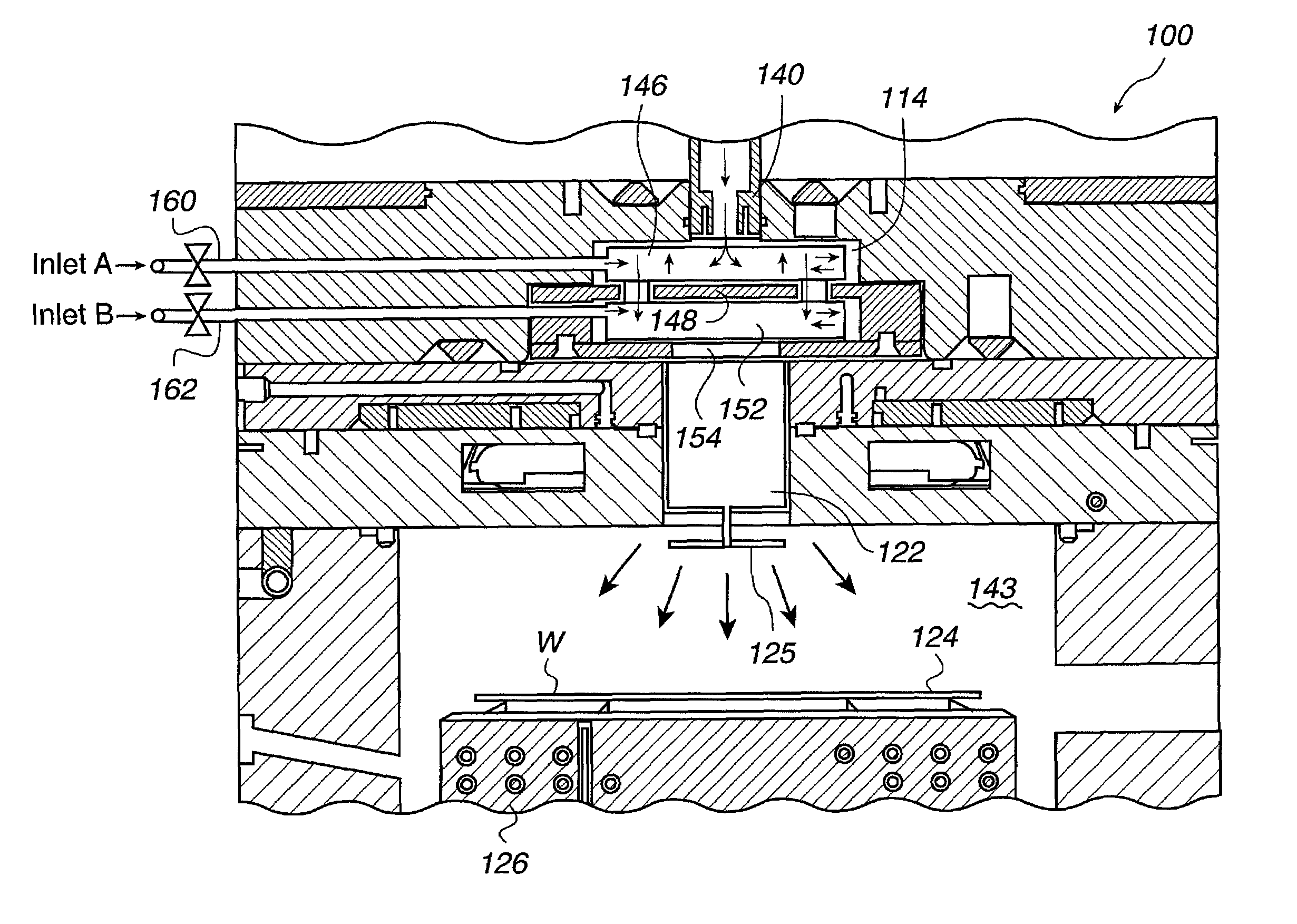
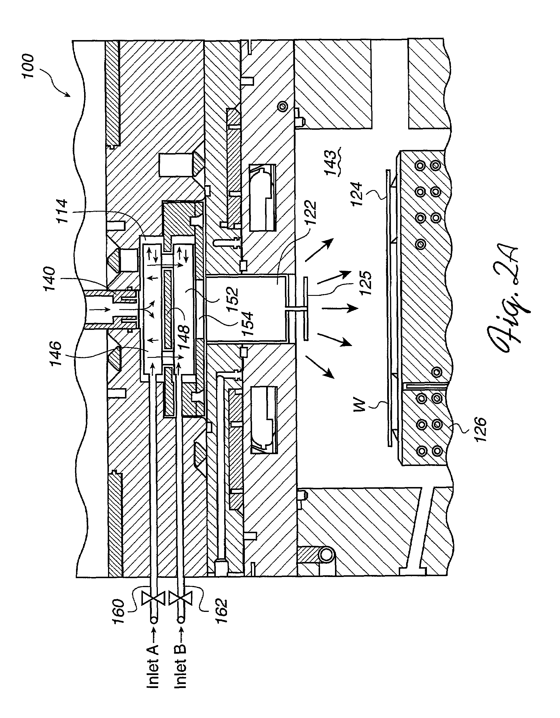
[0027]FIG. 2A is a simplified cross-sectional view of part of a Plasma Enhancement Platform (PEP) system 100 that is configured to include a downstream plasma optimization structure 114 with gas injection in accordance with one embodiment of the present invention. The downstream plasma optimization structure 114 therefore may function as a SCOPE having improved advantages described herein. As is known to those skilled in the art, the PEP system include a microwave (MW) downstream plasma source.

[0...


PUM

PropertyMeasurementUnit
distanceaaaaaaaaaa
surface areaaaaaaaaaaa
impedanceaaaaaaaaaa

Abstract

An apparatus for managing plasma in wafer processing operations is disclosed which includes a housing having an internal region defined by an inner wall. The housing has an input port for supplying a plasma into the housing at a first end and an output port at a second end. The apparatus includes a hollow tube contained in the internal region within the housing. The hollow tube is defined by a wall that extends between the first end and the second end and contains a plurality of orifices generating a plurality of fluid paths through the wall. A fluid input is included supplying fluid into the internal region of the housing. The supplied fluid is capable of passing through the plurality of orifices, and the plasma supplied through the input port is capable of being mixed within the hollow tube with the supplied fluid. The output port at the second end of the housing enables the mixed plasma and fluid supply to exit the housing.

Description

BACKGROUND OF THE INVENTION[0001]1. Field of the Invention[0002]This invention relates generally to the field of semiconductor equipment and more particularly concerns optimal methods and apparatus for processing wafers with use of downstream plasma and gas injection.[0003]2. Description of the Related Art[0004]Downstream plasma processing systems are often used to process semiconductor wafers or substrates for fabrication of integrated circuits. For example, downstream plasma processes are commonly used in etching, photoresist removal, chemical vapor deposition (CVD), etc. The downstream plasma processes are typically carried out by systems that generally include a plasma processing chamber to provide a controlled setting.[0005]The high temperatures produced within the plasma provide a source of convective heat transfer to the processing wafer. Subsequent heating of the wafer can produce wafer temperatures high enough to produce thermal damage to critical structures on the wafer, o...

Claims


Application Information

Patent Timeline
Patent Type & Authority Patents(United States)
IPC IPC(8): C23C16/511C23F1/00H01L21/306
CPCC23C16/452C23C16/45565H01J37/32357H01J37/32633C23C16/511H01L21/31116
Inventor SHEPHERD, JR., ROBERT A.CAUGHRAN, JAMES
Owner NOVELLUS SYSTEMS
Why Eureka
Try Eureka