
Heddle

a technology of heddles and heddles, which is applied in the field of heddles, can solve the problems of increasing the mass of a heddle, increasing the load on all the shedding devices, including the heddles, and increasing the load on the shedding device, so as to increase the load-bearing capacity, reduce the mass of the heddle, and increase the operating speed of the power loom

Inactive Publication Date: 2006-03-28
GROZ BECKERT KG
View PDF10 Cites 8 Cited by
  • Summary
  • Abstract
  • Description
  • Claims
  • Application Information

AI Technical Summary

Benefits of technology

[0007]The above object is attained by optimizing the heddles held by the shaft utilizing the various basic features of the invention, individually or in partial or full combination with one another, which leads to a reduction in the mass of a heddle while preserving its stability and optionally while increasing its load-bearing capacity. If all the claimed provisions are employed jointly, the result is a fully functional heddle with a weight that is about 20% below the usual standard. This makes a considerable increase in the operating speed of a power loom and / or a reduction in the load on the heddles possible.
[0008]One essential provision for improving the heddle is to provide one or more openings in the tapering end eyelet region, which compared to previously known heddles occupy an increased area. It has been demonstrated that more than one-eighth the total area of the tapering end eyelet region can be occupied by these openings. In preferred embodiments, the openings occupy an area which amounts to more than one-third and preferably more than half the total area of the tapering end eyelet region. If there are more than one opening, the spacing between them is preferably less than the length of one of the two openings. Preferably, the spacing is less than the length of the shorter opening. The weight reduction in the immediate vicinity of the end eyelet not only has a generally favorable effect but also reduces wear to a great extent. Simultaneously, the stability of the heddle is preserved entirely, particularly in the region of its end eyelet. The openings can lend the tapering end eyelet region a certain resilience and thus a buffer effect. With regard to impacts or shocks, the transition region can be considered a spring means.
[0009]Preferably, the tapering end eyelet region has an edge curved in an arc, whose radius is less than or equal to 60 mm. This provisions reduces the area of the tapering end eyelet region compared to conventional heddles, which contributes to reducing the weight without losing strength.

Problems solved by technology

This means increasingly longer shedding strokes and / or shortened motion times, and as a result the loads on all the shedding devices, which include the heddles, increase considerably and in fact disproportionately.

Method used


Image

  • Heddle
  • Heddle
  • Heddle

Examples


Embodiment Construction

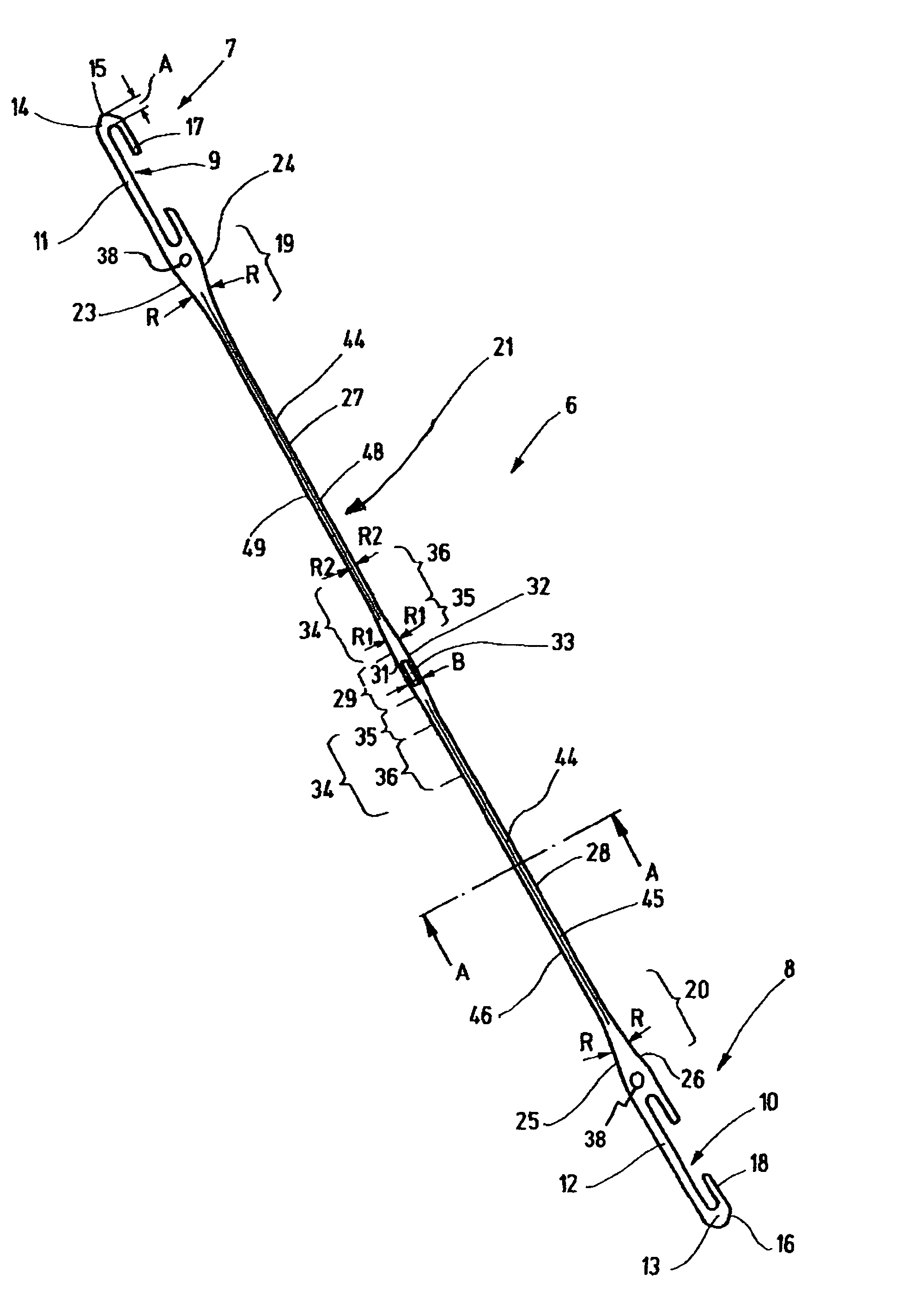
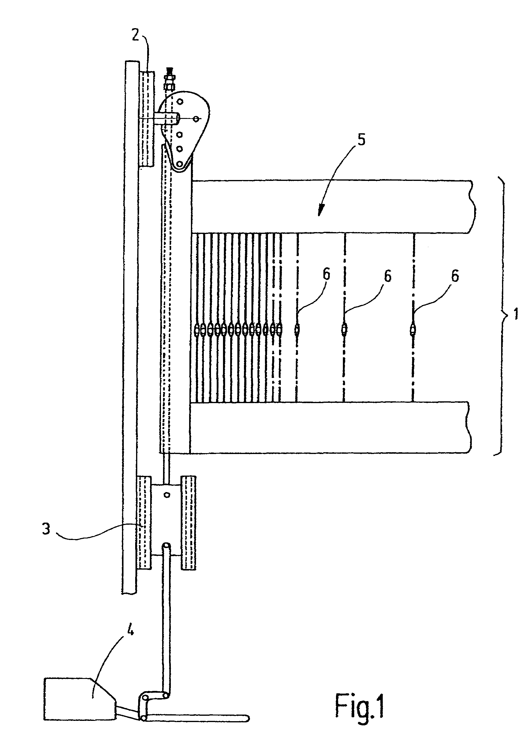
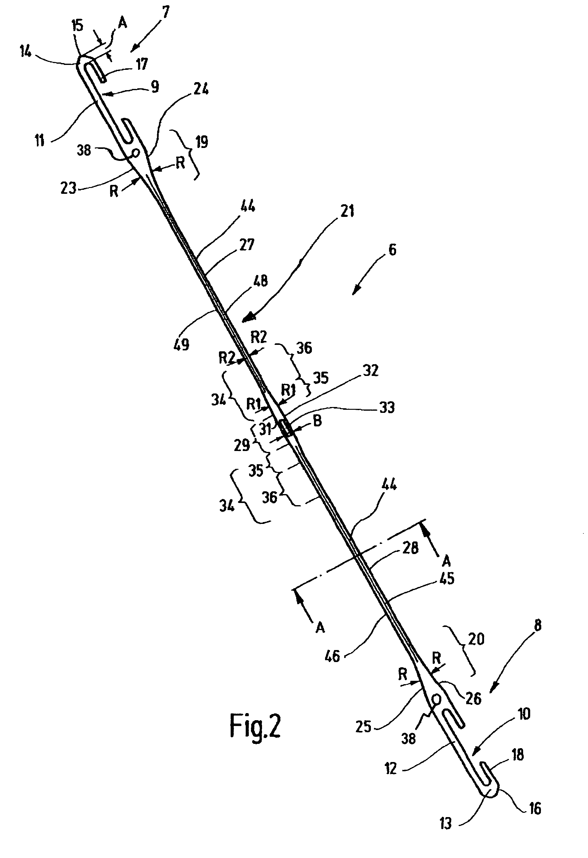
[0024]In FIG. 1, a heddle shaft 1 is shown which is vertically movably supported in a power loom. To that end, it is connected to a linear guide device 2, 3 and, via a suitable rod linkage, to a drive mechanism 4. The heddle shaft 1 forms a frame 5, on which heddles 6 are retained. The heddles serve to form sheds in a power loom. The heddles 6 are embodied identically to one another. For purposes of illustration, a single heddle 6 is shown in FIG. 2.

[0025]The heddle 6 is a one-piece sheet-metal part of elongated basic shape. On each end, the heddle 6 has a so-called end eyelet 7, 8, which is provided with an opening 9, 10, or so-called C-shaped jaw opening. Differently shaped openings 9, 10 are also known, such as J- and O-shaped openings. Each jaw opening 9, 10 is defined by a respective straight, parallel-edged, strutlike portion 11, 12, which is adjoined by portions 13, 14 (jaw end region) extending in the form of a U. The portions 13, 14 each form one jaw end region. This region...


PUM


Abstract

In a heddle (6), the slender heddle shank (21) has been lengthened, at the cost of the end eyelets (7, 8) and the yarn eyelet region (29). This is accomplished on the one hand by shortening the end eyelet regions (7, 8) to their absolute minimum length and on the other by placing the auxiliary openings (38), which serve to transport the heddles, closer to the end eyelets (7, 8). The radii R in the region of the end eyelets (7, 8) are reduced. Instead of the usual 2 mm width, the heddle shank (21) still has a maximum width of 1.6 mm. The regions (14, 13) of the heddle (6) that protrude past the end openings still have, instead of the usual length of 4 mm, a length of 2.5 mm to 3 mm. Directly around the yarn eyelet (33), the heddle has a width which, as before, is equivalent to twice the width of the yarn eyelet (33). However, the length of this region is shortened to a maximum of twice to three times the yarn eyelet width. The transition from the narrowest zone (27, 28) of the heddle shank (21) to the comparatively wide zone (29) around the yarn eyelet (33) is characterized by an elongated transition region (34), which has a maximum width of 1.8 mm and serves to reinforce this region against mechanical stresses.

Description

CROSS REFERENCE TO RELATED APPLICATIONS[0001]This application claims the priority of German Patent Application No. 103 30 304.9, filed on Jun. 17, 2003, the subject matter of which, in its entirety, is incorporated herein by reference.BACKGROUND OF THE INVENTION[0002]The invention relates to a heddle, in particular for power looms.[0003]Power loom heddles are known per se. As a rule, they have an elongated body, shaped from a metal sheet, with so-called end eyelets embodied on their upper and lower ends; these eyelets serve to secure them to the support rail of a heddle shaft. The heddle is provided approximately in the middle with a yarn eyelet, which serves to guide a warp thread. By suitable longitudinal motion of all the heddles, shedding is accomplished in the loom.[0004]Similar heddles are in use for jacquard machines. However, they are retained individually on harness yarns or so-called laces and are tensed by a spring.[0005]Power looms with heddles retained on a shaft are to...

Claims


Application Information

Patent Timeline
IPC IPC(8): D03C9/00D03C9/02D03C9/04D03C9/06
CPCD03C9/02D03C9/065D03C9/024
Inventor METTLER, FRANZSCHWANE, HERBERT
Owner GROZ BECKERT KG
Learn More