Method and apparatus for transporting pressurized gas canisters

Inactive Publication Date: 2006-03-28
WILLIAMSON JOHN P
View PDF8 Cites 45 Cited by
  • Summary
  • Abstract
  • Description
  • Claims
  • Application Information

AI Technical Summary

Benefits of technology

[0010]One or more inclined structural members connect the upper

Problems solved by technology

A problem exists in the safe and economical transport of supplies to offshore oil and gas well drilling and production platforms.
A particular problem is the tr

Method used


Image

  • Method and apparatus for transporting pressurized gas canisters
  • Method and apparatus for transporting pressurized gas canisters
  • Method and apparatus for transporting pressurized gas canisters

Examples


Embodiment Construction

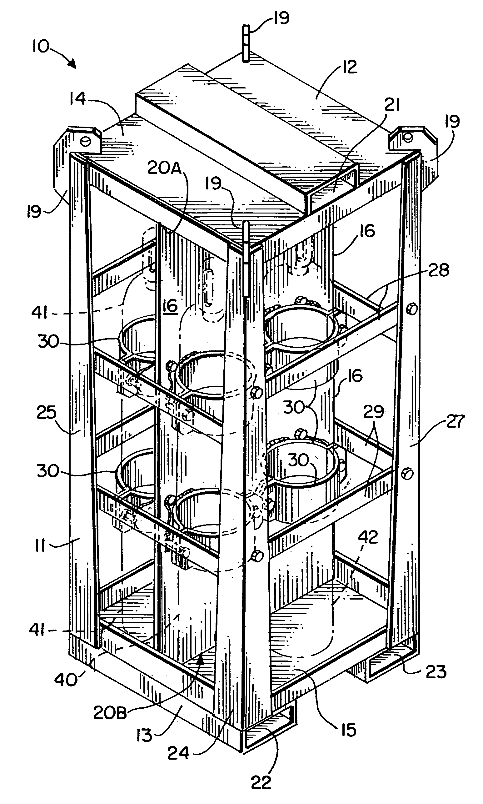
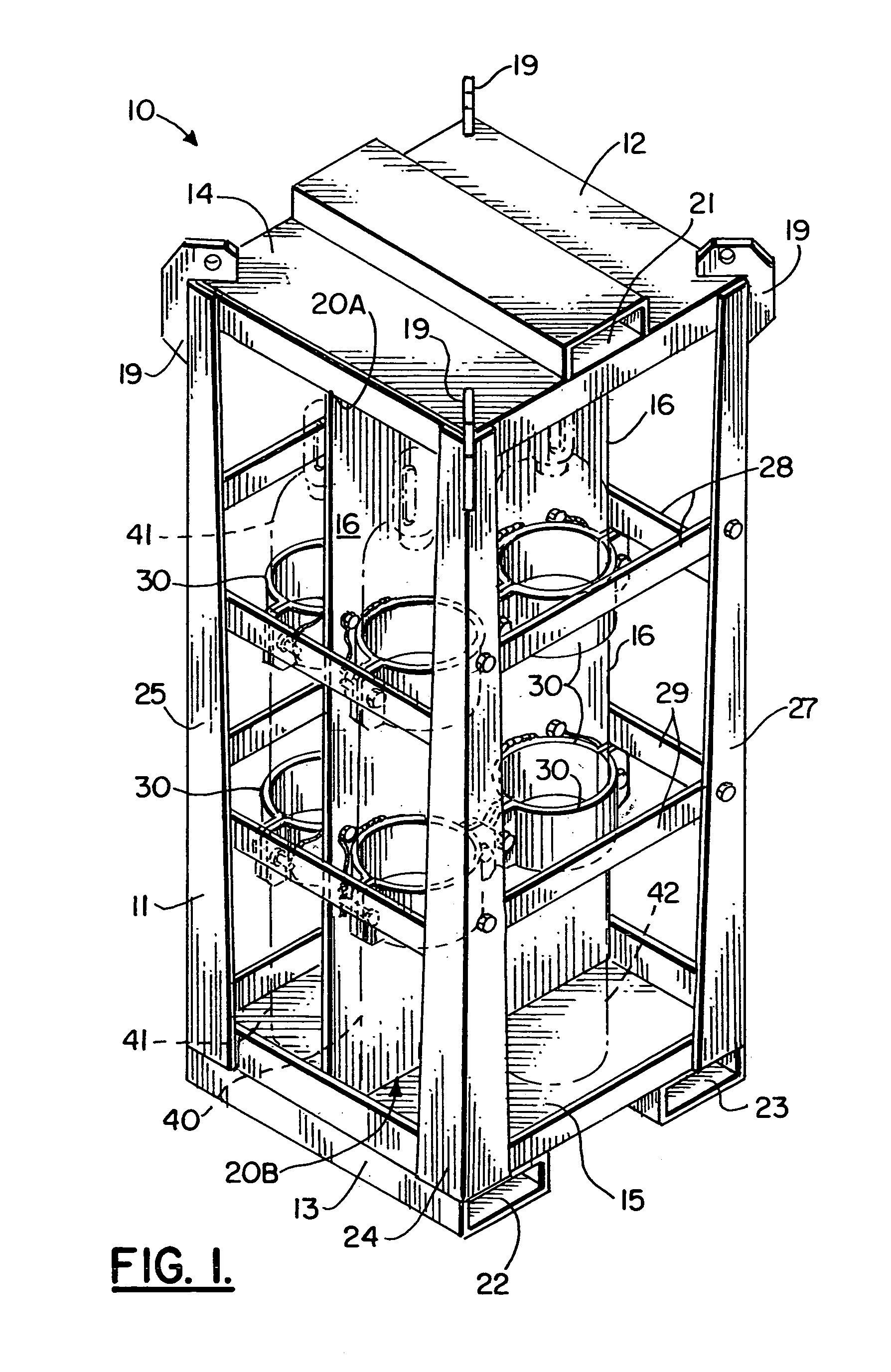
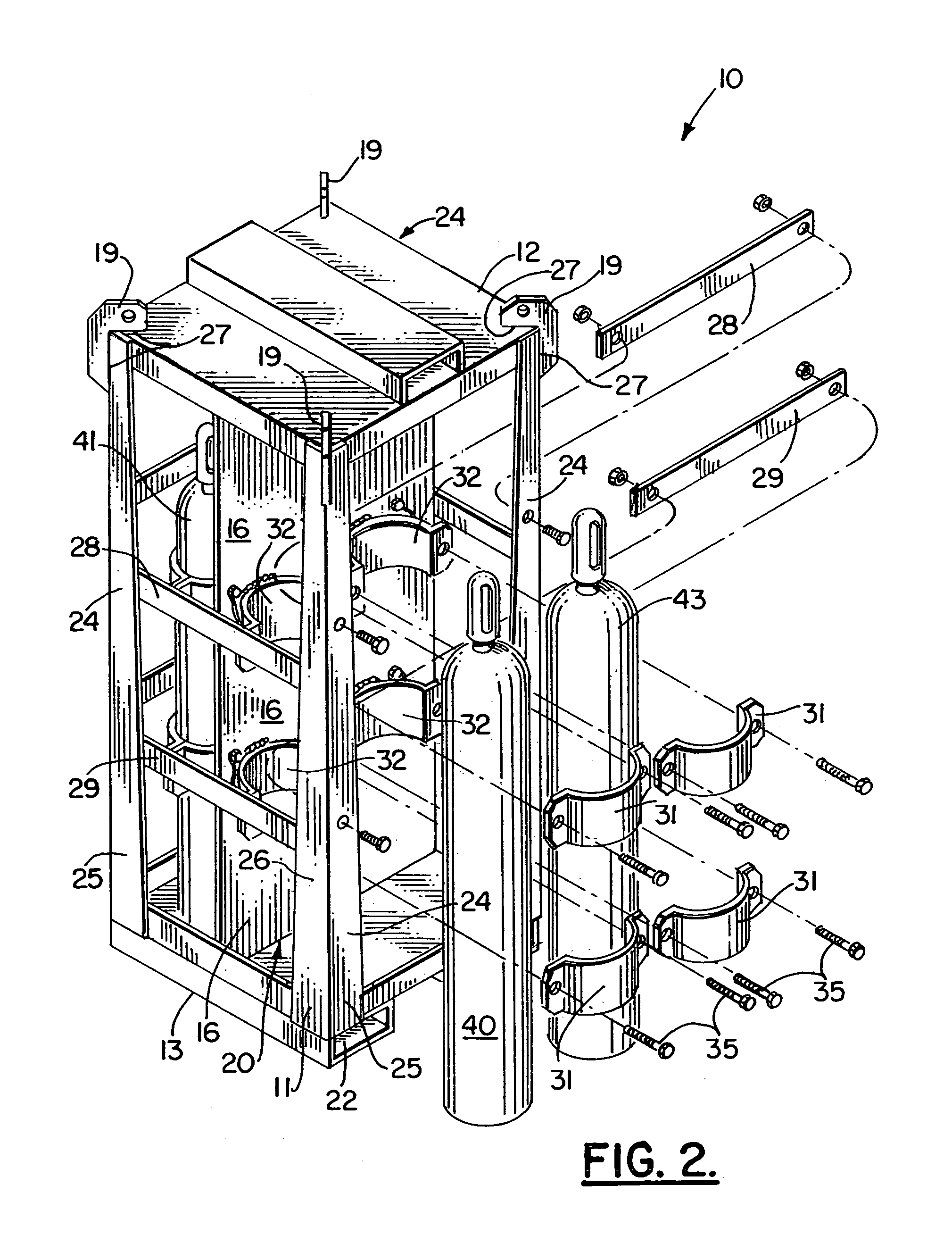
[0026]Gas canister transport apparatus 10 is shown in FIGS. 1–2. The apparatus 10 includes a frame 11 having an upper end portion 12 and a lower end portion 13. Frame 11 includes an upper panel 14 and a lower panel 15 connected with a central vertically extending panel 16. Lower panel 15 can be reinforced with beams, transverse plates, or the like to help support the weight of cannisters 4043. An upper welded connection 20A joins the upper panel 14 to the central panel 16. A lower welded connection 20B preferably joins the central panel 16 to the lower panel 15.

[0027]A plurality of lifting eyes 19 are provided on the upper panel 14 for enabling a sling or a plurality of slings to be fitted to the apparatus 10 at the lifting eyes 19 so that the apparatus 10 can be lifted with a crane or like lifting device. Each lifting eye preferably connects at weld 27 to both top panel 12 and a column 24.

[0028]A plurality of forklift receptacle openings 21–23 are provided that enable a forklift to...


PUM


Abstract

The present invention discloses a pressurized gas canister transport apparatus and a method of use. The apparatus includes a frame that is specially configured to carry a plurality of generally cylindrically shaped pressurized gas canisters. The frame features upper and lower panels that are connected to a central panel, the central panel providing structural reinforcement and also separating selected canisters from one another, such as oxygen canisters from canisters containing combustible materials. A clamping arrangement is provided for safely holding the canisters in position. In addition, should the canisters become dislodged from their clamps, an additional safety arrangement is provided in the form of railings that are transversely extending and which span between corner columns of the frame to prevent escape of canisters even if they become dislodged from their clamps.

Description

CROSS-REFERENCE TO RELATED APPLICATIONS[0001]Priority of U.S. Provisional Patent Application Ser. No. 60 / 413,103, filed Sep. 24, 2002, incorporated herein by reference, is hereby claimed.STATEMENT REGARDING FEDERALLY SPONSORED RESEARCH OR DEVELOPMENT[0002]Not applicableREFERENCE TO A “MICROFICHE APPENDIX”[0003]Not applicableBACKGROUND OF THE INVENTION[0004]1. Field of the Invention[0005]The present invention relates to cargo transportation racks and more particularly to an improved transport apparatus for transporting pressurized gas canisters.[0006]2. General Background of the Invention[0007]In the offshore oil and gas well drilling and production industries, there are a number of oil and gas well drilling and production facilities located in a marine environment. Many of these facilities are offshore oil and gas well drilling and production platforms located in very deep water. They are often many miles from the nearest port.[0008]A problem exists in the safe and economical transp...

Claims


Application Information

Patent Timeline
IPC IPC(8): B65D19/00
CPCF17C13/084F17C2205/0192F17C2201/0109F17C2201/0119F17C2201/032F17C2201/058F17C2270/05F17C2205/013F17C2205/0157F17C2205/0308F17C2221/011F17C2223/0123F17C2205/0107
Inventor WILLIAMSON, JOHN P.
Owner WILLIAMSON JOHN P
Why Eureka
Try Eureka