
Low cost RFID antenna manufactured from conductive loaded resin-based materials

a technology of conductive resin and rfid antenna, which is applied in the direction of resonant antennas, protective materials, instruments, etc., can solve the problems of large coils and high manufacturing costs, disadvantages of conductive ink, and inability to meet the requirements of a wide range of applications, and achieve the effect of effective rfid

Inactive Publication Date: 2006-03-28
INTEGRAL TECHNOLOGY INC
View PDF12 Cites 116 Cited by
  • Summary
  • Abstract
  • Description
  • Claims
  • Application Information

AI Technical Summary

Benefits of technology

[0016]A yet further object of the present invention is to provide a RFID antenna molded of conductive loaded resin-based material where the antenna characteristics can be altered or the visual characteristics can be altered by forming a metal layer over the conductive loaded resin-based material.

Problems solved by technology

Conversely, in very cost sensitive applications, such as retail pricing and security tags, the RFID transponder device must be as inexpensive as possible and, therefore, must be a passive system.
Coils are large and expensive to manufacture.
However, the manufacturing cost is still too high for many applications.
However, conductive ink has disadvantages.
First, conductive inks are of higher resistivity than metal and, therefore, result in lossy antennas.
Conductive ink antennas provide reduced system performance due to resistive losses.
Second, spiral conductive ink antennas require two conductive ink layers separated by an insulating ink layer to complete the circuit connectivity.
As a result, the manufacturing process can be complex and expensive.

Method used


Image

  • Low cost RFID antenna manufactured from conductive loaded resin-based materials
  • Low cost RFID antenna manufactured from conductive loaded resin-based materials
  • Low cost RFID antenna manufactured from conductive loaded resin-based materials

Examples


Embodiment Construction

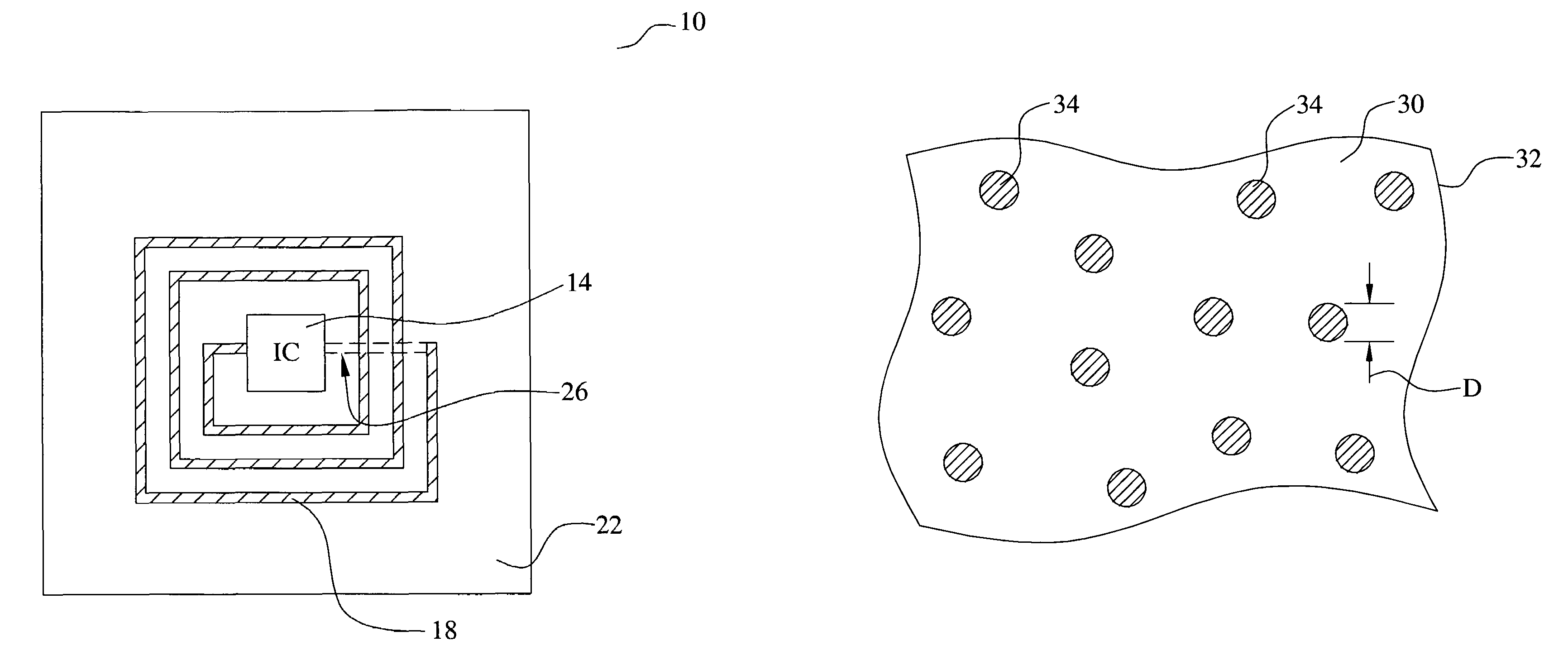
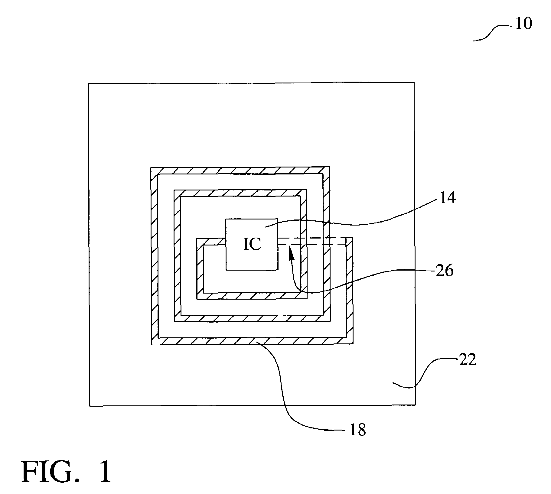
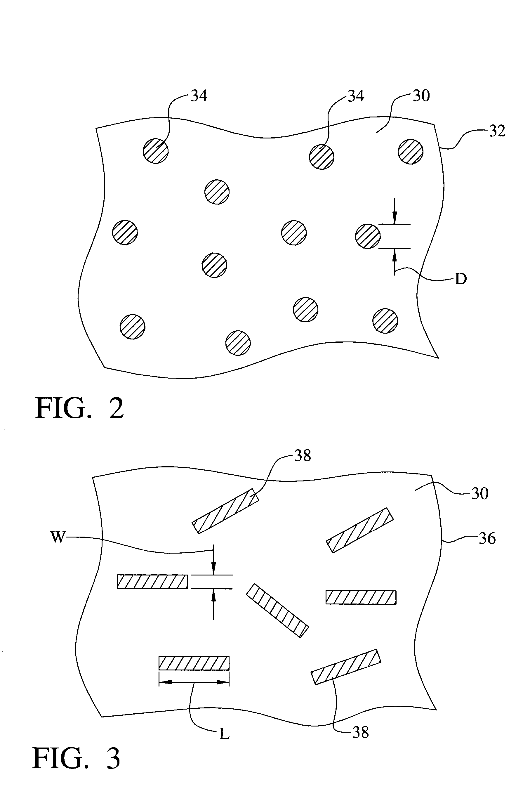
[0039]This invention relates to RFID devices molded of conductive loaded resin-based materials comprising micron conductive powders, micron conductive fibers, or a combination thereof, homogenized within a base resin when molded.

[0040]The conductive loaded resin-based materials of the invention are base resins loaded with conductive materials, which then makes any base resin a conductor rather than an insulator. The resins provide the structural integrity to the molded part. The micron conductive fibers, micron conductive powders, or a combination thereof, are homogenized within the resin during the molding process, providing the electrical continuity.

[0041]The conductive loaded resin-based materials can be molded, extruded or the like to provide almost any desired shape or size. The molded conductive loaded resin-based materials can also be cut, stamped, or vacuumed formed from an injection molded or extruded sheet or bar stock, over-molded, laminated, milled or the like to provide...


PUM

PropertyMeasurementUnit
diameteraaaaaaaaaa
diameteraaaaaaaaaa
lengthaaaaaaaaaa

Abstract

RFID antennas are formed of a conductive loaded resin-based material. The conductive loaded resin-based material comprises micron conductive powder(s), conductive fiber(s), or a combination of conductive powder and conductive fibers in a base resin host. The percentage by weight of the conductive powder(s), conductive fiber(s), or a combination thereof is between about 20% and 50% of the weight of the conductive loaded resin-based material. The micron conductive powders are formed from non-metals, such as carbon, graphite, that may also be metallic plated, or the like, or from metals such as stainless steel, nickel, copper, silver, that may also be metallic plated, or the like, or from a combination of non-metal, plated, or in combination with, metal powders. The micron conductor fibers preferably are of nickel plated carbon fiber, stainless steel fiber, copper fiber, silver fiber, or the like.

Description

[0001]This Patent Application claims priority to the U.S. Provisional Patent Application 60 / 499,427, filed on Sep. 2, 2003, which is herein incorporated by reference in its entirety.[0002]This Patent Application is a Continuation-in-Part of U.S. patent application Ser. No. 10 / 309,429, filed on Dec. 4, 2002 now U.S. Pat. No. 6,870,516, also incorporated by reference in its entirety, which is a Continuation-in-Part application, filed as U.S. patent application Ser. No. 10 / 075,778, filed on Feb. 14, 2002 now U.S. Pat. No. 6,741,221, which claimed priority to U.S. Provisional Patent Applications Ser. No. 60 / 317,808, filed on Sep. 7, 2001, Ser. No. 60 / 269,414, filed on Feb. 16, 2001, and Ser. No. 60 / 268,822, filed on Feb. 15, 2001.BACKGROUND OF THE INVENTION[0003](1) Field of the Invention[0004]This invention relates to radio frequency identification devices and, more particularly, to radio frequency identification devices molded of conductive loaded resin-based materials comprising micr...

Claims


Application Information

Patent Timeline
Patent Type & Authority Patents(United States)
IPC IPC(8): G06K19/00B29C45/00G06K19/077H01Q1/12H01Q1/22H01Q1/24H01Q1/32H01Q1/36H01Q1/38H01Q1/40H01Q7/00H01Q9/04H01Q9/16H01Q9/30H01Q21/00H05K1/09H05K3/10
CPCG06K19/07749G06K19/07779G06K19/07783G08B21/0297H01Q1/22H01Q1/2225H01Q1/36H01Q1/364H01Q1/38H01Q7/00H05K3/101B29C45/0013B29C45/0001H05K2203/0113B29K2995/0005B29L2031/3456H05K1/095H05K3/107H05K2201/0281H05K2201/09118
Inventor AISENBREY, THOMAS
Owner INTEGRAL TECHNOLOGY INC
Learn More