Airfoil surface impedance modification for noise reduction in turbofan engines

a technology of airfoil surface impedance and turbofan engine, which is applied in the direction of marine propulsion, vessel construction, other chemical processes, etc., can solve the problems of large weight increase at high bypass ratio, difficult to meet the requirements of high-efficiency turbine engines, and high noise of fan noise. achieve the effect of reducing noise in gas turbine engines

Active Publication Date: 2006-03-28
RTX CORP
View PDF3 Cites 28 Cited by
  • Summary
  • Abstract
  • Description
  • Claims
  • Application Information

AI Technical Summary

Benefits of technology

[0009]Accordingly, it is an object of the present invention to provide an aircraft engine component which reduces noise in gas turbine engines.
[0010]It is a further object of the present invention to provide an aircraft engine component wherein the noise reduction means produces large (predictable) changes in the unsteady loading, while having little effect on the steady loading.
[0012]In accordance with the present invention, an aircraft engine component is provided which reduces noise in turbofan engines. The aircraft engine component broadly comprises having a first aerodynamic surface, a second aerodynamic surface, and means for reducing noise without altering a pressure differential between the first aerodynamic surface and the second aerodynamic surface.

Problems solved by technology

A sizeable portion of this noise is tonal in nature and can be partially attributed to the unsteady aerodynamic interaction between the stator and wakes shed from the upstream rotor.
As one increases bypass ratio, fan noise is likely to be the dominant source.
Some of these techniques however may not always be applicable.
Duct liners suffer from the drawback that the thickness required to provide significant noise attenuation may be quite large, resulting in large weight increase at high bypass ratios.
In particular, the amount of flow turning in the exit guide vane should not be affected, nor the flow losses enhanced to any significant extent, for this would result in degraded performance.
Thus, the system shown in U.S. Pat. No. 6,139,259 to Ho et al., wherein the pressure and suction surfaces of the exit guide vane (or strut) communicate through small channels over the entire leading edge surface of the airfoil, is not feasible since it would alter both the mean and unsteady loading.

Method used


Image

  • Airfoil surface impedance modification for noise reduction in turbofan engines
  • Airfoil surface impedance modification for noise reduction in turbofan engines
  • Airfoil surface impedance modification for noise reduction in turbofan engines

Examples


first embodiment

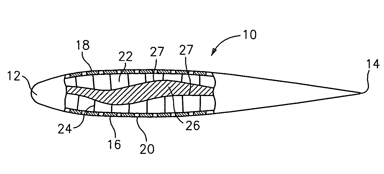
[0018]Referring now to the drawings, FIG. 1 illustrates an engine component 10 having a means for reducing the noise generated by a gas turbine engine. The component 10 may be a vane or a blade used in the engine. As can be seen from FIG. 1, the component 10 has a leading edge 12, a trailing edge 14, and a first surface 16 and a second surface 18 which extend from the leading edge 12 to the trailing edge 14. Each of the surfaces 16 and 18 has a plurality of perforations or apertures 20. The component 10 is divided into a plurality of cells 22 by transverse elements 24 and a contoured backing 26. The contoured backing 26 may be an acoustic liner formed from any suitable metallic or non-metallic material known in the art. The depth of each cell 22 is varied by the shape of the backing 26 which varies in the chordwise direction.

[0019]In operation, a fluid, such as air, flows over the surfaces 16 and 18 and enters the cells 22. The presence of the backing 26 prevents the air from passin...

third embodiment

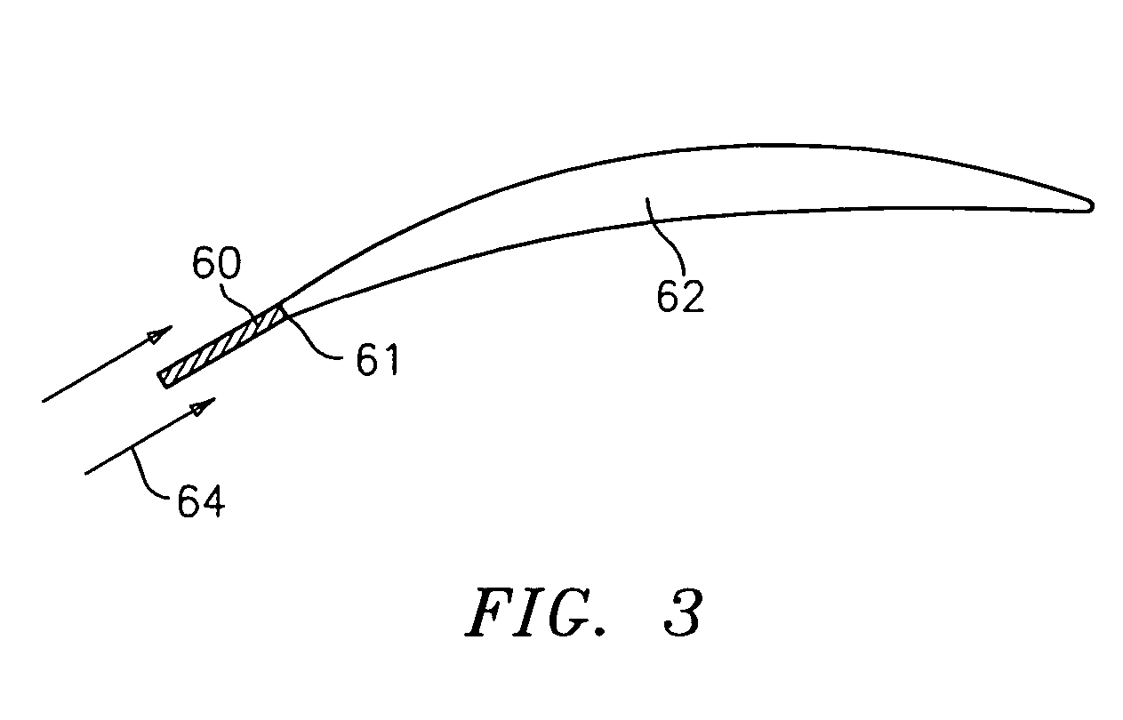
[0022]a noise reduction technique is illustrated in FIG. 3. In this embodiment, a short length plate 60 of uncambered, porous material is attached to the leading edge 61 of an airfoil portion 62 of an engine component. The plate 60 is oriented parallel to the mean flow direction 64. Unlike the previous embodiments, the flows streams on either side of the plate 60 now communicate with each other. However, because of the orientation of the plate 60 along the inflow direction, its impact on the steady loading is minimal. Unsteady disturbance such as those induced by incoming rotor wakes will however be significantly affected by the impedance of the plate 60. This will have an effect on the unsteady airfoil loading and thus the noise that is generated. Despite a superficial resemblance to the device shown in U.S. Pat. No. 6,139,259 to Ho et al., the fundamental difference here is that the resistive element is not contained within the working portion of the airfoil, i.e. within the zone ...


PUM


Abstract

In accordance with the present invention, an aircraft engine is provided with a component which helps reduce the noise generated by the engine. The component has a first aerodynamic surface, a second aerodynamic surface, and a system for reducing noise without altering a pressure differential between the first aerodynamic surface and the second aerodynamic surface.

Description

STATEMENT OF GOVERNMENT INTEREST[0001]The Government of the United States of America may have rights in the present invention as a result of Contract No. NAS3-98005 awarded by the National Aeronautics and Space Administration.BACKGROUND OF THE INVENTION[0002](a) Field of the Invention[0003]The present invention relates to a component for use in a gas turbine engine, particularly turbofan engines, which component is provided with means for reducing noise generated by said engine.[0004](b) Prior Art[0005]The noise generated by contemporary turbofan engines has a significant economic impact. This is because aircraft operations are restricted to specific times during the day which prevents, for instance, 24-hour use of freight carriers. A sizeable portion of this noise is tonal in nature and can be partially attributed to the unsteady aerodynamic interaction between the stator and wakes shed from the upstream rotor. As one increases bypass ratio, fan noise is likely to be the dominant s...

Claims


Application Information

Patent Timeline
Patent Type & Authority Patents(United States)
IPC IPC(8): F04D29/66F01D5/10F01D5/16F01D5/18F01D25/00F02K3/02F04D29/38F04D29/54
CPCF01D5/16F01D5/18F04D29/324F04D29/667Y10S416/50Y02T50/671Y02T50/673Y02T50/676F05D2260/96F05D2270/17Y02T50/60
Inventor PRASAD, DILIPMORIN, BRUCE L.LORD, WESLEY K.MATHEWS, DOUGLAS C.
Owner RTX CORP
Why Eureka
Try Eureka