Endoscope assembly useful with a scope-sensing light cable

a technology of endoscope and light cable, which is applied in the field of endoscopes, can solve the problems of large amount of light energy required by the light source of an endoscopic, drapes that may either burn or ignite, and energy may singe the drape, so as to reduce the extent of light emitted

Inactive Publication Date: 2006-03-28
STRYKER CORP
View PDF32 Cites 123 Cited by
  • Summary
  • Abstract
  • Description
  • Claims
  • Application Information

AI Technical Summary

Benefits of technology

[0009]This invention relates generally to an improved endoscope with integrated light source designed to reduce the extent to which the light emitted by the light source has the potential for being a thermal hazard in a surgical suite. This invention also relates to a light source capable of receiving a signal representative of the type of light source to which it is connected. Based on this information, the light source of this invention is able to both initially establish the light it emits and the extent and rate at which it adjusts the emitted light. This invention also relates generally to an improved endoscope capable of providing an indication of its specific type.

Problems solved by technology

One particular disadvantage relates to the fact that, in order to illuminate a surgical site, the light source for an endoscopic is required to transmit a large amount of light energy.
Problems arise with these light sources because, during endoscopic surgery, it may be necessary to switch the endoscope that is used on a patient.
A problem can occur because the light energy emitted by the fiber optic cable can rapidly warm the surface on which the distal end of the cable is placed.
If the surface is cloth or paper, such as a surgical drape, there is a potential that this energy may singe the drape.
If the fiber optic cable is inadvertently left on the drape for an extended period of time, the heat generated could potentially cause the drape to either burn or ignite.
Moreover, another problem associated with illuminating the surgical site during an endoscopic surgical procedure is that the light directed towards the site invariably changes during the course of the procedure.
If the quantity of received light becomes relatively high, the view of the site is lost due to white-out.
If the amount of light per unit surface area appreciably diminishes, the view of the site significantly darkens.
In either situation, the surgeon's view of the surgical site may decay to the point at which it the ability to perform the surgical procedure is hampered.
Moreover, even minor changes in the light present at the surgical field may be distracting.
While the above feedback circuits work reasonably well, there are some limitations associated with current light sources.
Requiring surgical personnel to perform this procedure can increase the time it takes for the overall surgical task to be accomplished.
Moreover, since this procedure is performed manually, there is always the possibility that this procedure will either not be performed, or performed incorrectly.
In either situation, until the light source feedback circuit receives a correct indication of the type of endoscope to which the light source is connected, the source may output light that is inappropriate for the endoscope with which it is used.

Method used


Image

  • Endoscope assembly useful with a scope-sensing light cable
  • Endoscope assembly useful with a scope-sensing light cable
  • Endoscope assembly useful with a scope-sensing light cable

Examples


Embodiment Construction

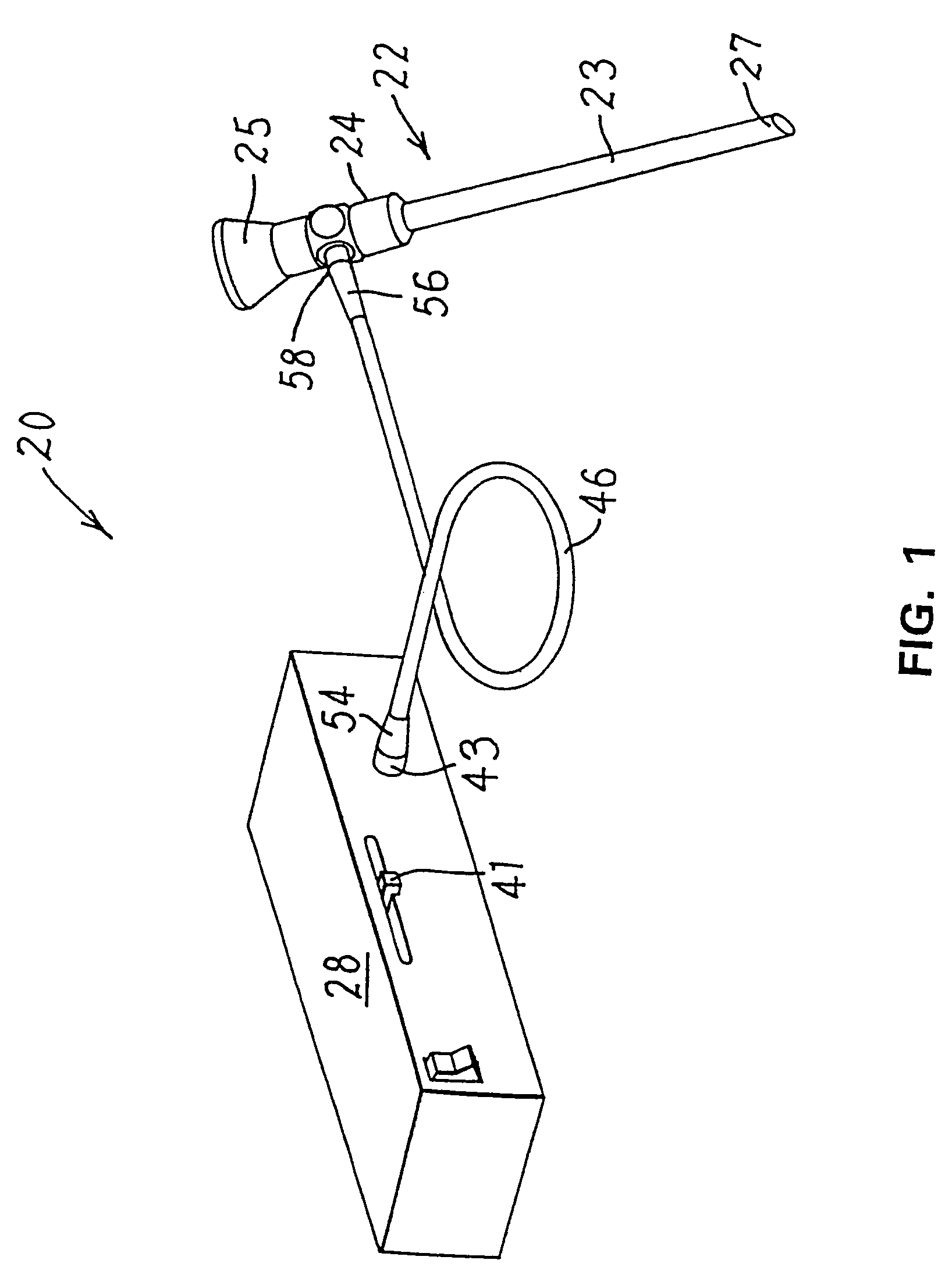
[0055]FIG. 1 illustrates the basic features of the endoscopic system 20 of this invention. The endoscopic system 20 includes an endoscope 22. The endoscope has an elongated hollow shaft 23 with a distal end 27 that is positioned inside the body of the patient. A window, not illustrated covers the distal end of the shaft 23. The shaft 23 also has a proximal end 24 that remains outside of the patient. An eyepiece 25 is fitted over the proximal end 24 to provide a viewing port through which the surgeon views the surgical field. Optical focusing elements, not illustrated, in the shaft 23 serve to enhance the visible field of view. The eyepieces 25 of many endoscopes are designed to hold a television camera. These cameras provide surgical personnel with a view of the surgical site on complementary monitors to which they are connected.

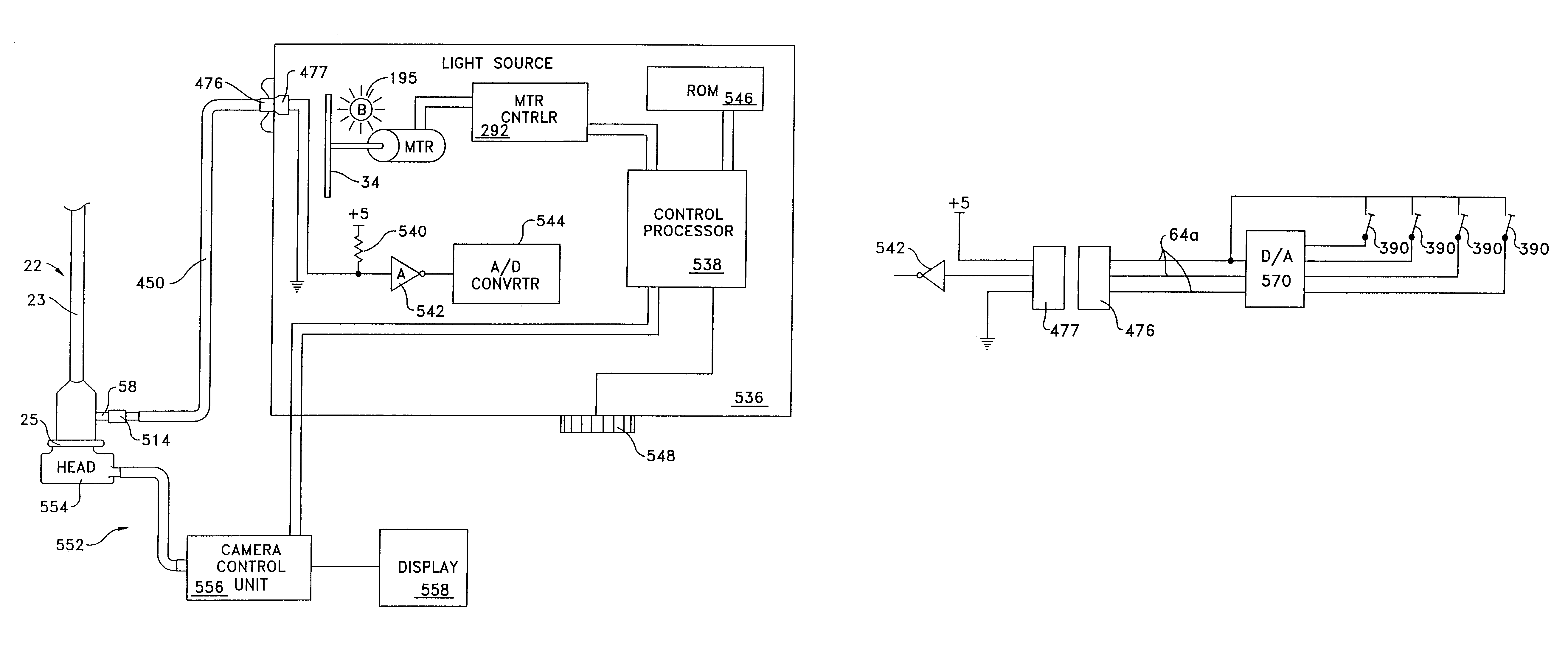
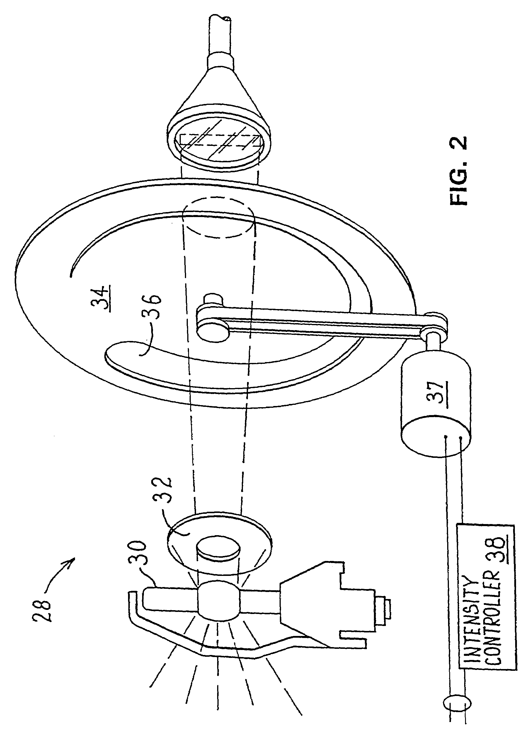
[0056]Endoscopic system 20 includes a light source 28 for illuminating the surgical site. As seen by reference to FIG. 2, light source 28 includes a bulb 30...


PUM


Abstract

An endoscope assembly consisting of an endoscope 622, a light source, 626 and a camera 552 with display 558. The endoscope contains a memory 670 with data that describes the endoscope and its operating characteristics. When the light source is connected to the endoscope with a fiber optic cable 628, the data in the memory are read into a control processor 538a internal to the light source. The control processor, based on the endoscope data configures the light source so that it emits an appropriate amount of light for that endoscope. The light source also sends a control unit 556 of the camera data indicating the type of endoscope to which the camera is attached. Based on this endoscope type data, the control unit processes the image signals generated by the camera head in an appropriate form for the attached endoscope so as to produce appropriate signals for presenting an image on the display.

Description

RELATIONSHIP TO EARLIER FILED APPLICATIONS[0001]This application is a continuation-in-part of U.S. patent application Ser. No. 09 / 628,488, filed Jul. 31, 2000 now U.S. Pat. No. 6,689,050. Pursuant to 35 U.S.C. Secs. 120 and 365, the Applicants hereby, to the extent possible, claim, for the present application, the filing date of Application Ser. No. 09 / 628,488, and the applications from which it claims priority. The '488 Application is continuation-in-part of Application Ser. No. 09 / 131,067, filed Aug. 7, 1998, now U.S. Pat. No. 6,110,107. The '067 Application is a continuation-in-part from Application Ser. No. 08 / 886,955, filed Jul. 2, 1998, now U.S. Pat. No. 5,850,496. The '955 Application claims priority from United States Provisional Patent Application Ser. No. 60 / 024,198, filed Aug. 26, 1996. The Applicants hereby incorporate by reference the contents of U.S. Pat. No. 6,110,107, entitled FIBER OPTIC CABLE FOR SUPPLYING LIGHT TO AN ENDOSCOPE AND FOR DETECTING THE PRESENCE OF AN ...

Claims


Application Information

Patent Timeline
Patent Type & Authority Patents(United States)
IPC IPC(8): A61B1/07A61B1/04G02B6/36A61B1/045
CPCA61B1/00059A61B1/00117A61B1/07A61B1/0669A61B1/045A61B1/042Y10T403/20A61B1/0655
Inventor CHANG, HUEI LIANGBEUTTER, RICHARD A.
Owner STRYKER CORP
Why Eureka
Try Eureka