Splittable multilumen catheter assembly

a multi-lumen, catheter technology, applied in the direction of multi-lumen catheters, catheters, other medical devices, etc., can solve the problems of increasing the attendant risks of catheterization procedures, the catheter tube leakage potential, and the catheter only being inserted. , to achieve the effect of convenient catheter insertion, efficient fluid flow properties, and facilitating leakage prevention

Inactive Publication Date: 2006-03-28
MEDICAL COMPONENTS INC
View PDF89 Cites 78 Cited by
  • Summary
  • Abstract
  • Description
  • Claims
  • Application Information

AI Technical Summary

Benefits of technology

[0014]The present invention is a multilumen catheter assembly which provides easy catheter insertion by a single tunneling procedure and assists the prevention of leakage at the site of vessel entry through use of a unitary, outer wall configuration. The catheter assembly also provides independent, free floating movement within the vessel through use of separate, distal end catheter tubes and provides efficient fluid flow properties within lumens of the catheter assembly.

Problems solved by technology

However, this technique is only possible in cases where the catheter is of a relatively small diameter, made of a stiff material and not significantly larger than the guide wire, for example, for insertion of small diameter dual lumen catheters.
The Tesio double catheter assembly, while comfortable for the patient, due to its soft durometer, and very effective for hemodialysis, typically requires multiple procedures and incisions for insertion and / or for tunneling, which increase the attendant risks of the catheterization procedure.
Further, in the case of side-by-side placement of two catheter tubes through a single insertion site in a vessel, while minimizing the number of procedures, can present a potential for leakage between the catheter tubes at the point where the catheter tubes pass into the vessel.
Further, the softer durometer of such catheters, which are typically made of a silicone or a similar material, reduces the risk of vessel wall damage.
Further, since the retaining sleeve is located outside the vessel when in place to provide the self-retaining feature, at the point of entry into the vessel, the catheters are side-by-side in the manner of a standard Tesio catheter, and there still remains the potential risk of blood leakage between the catheters at the vessel site.

Method used


Image

  • Splittable multilumen catheter assembly
  • Splittable multilumen catheter assembly
  • Splittable multilumen catheter assembly

Examples


first embodiment

A First Embodiment

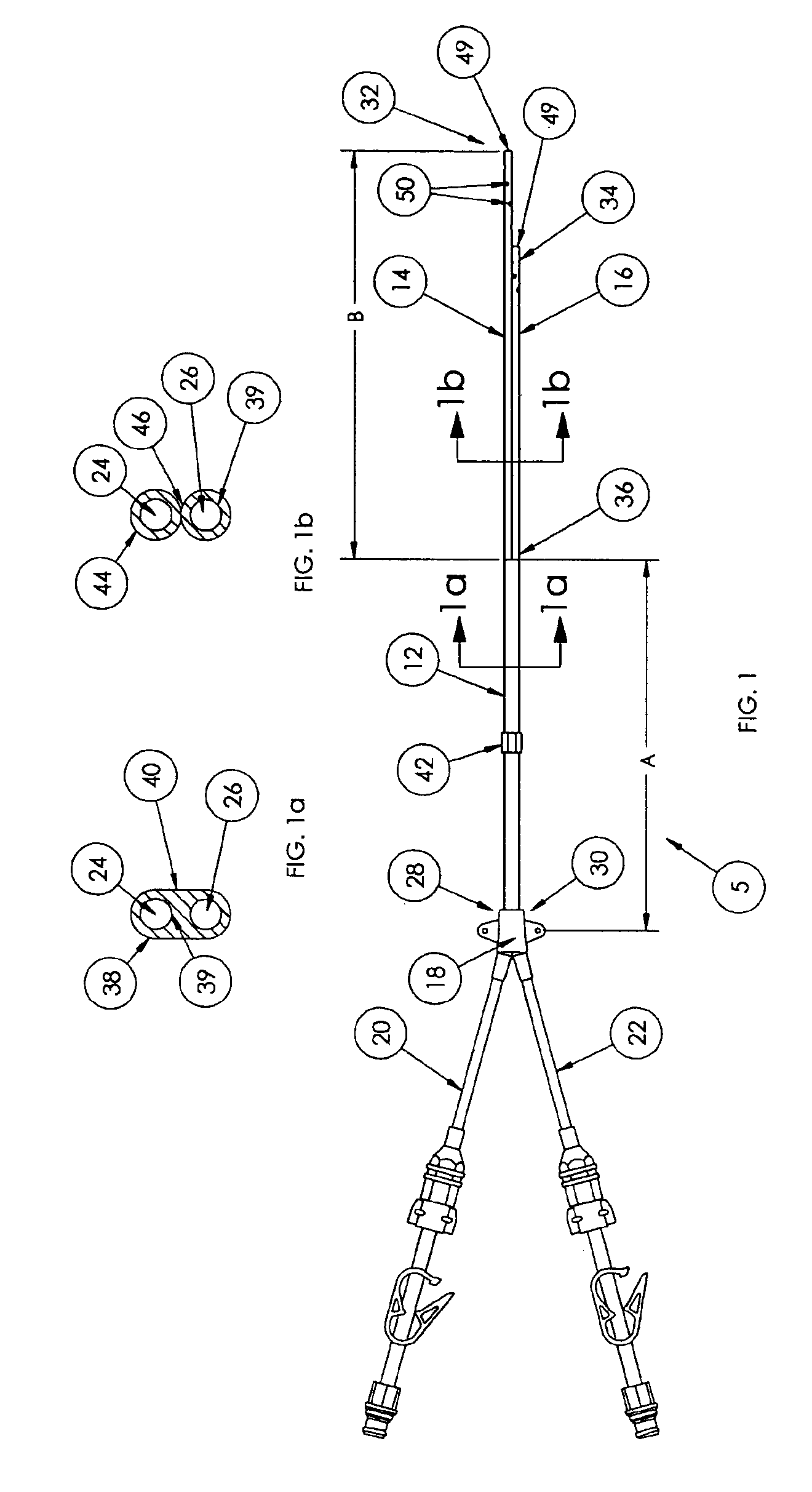
[0050]FIG. 1 illustrates one embodiment of the present invention, where a catheter assembly 5 has at least two lumens. The illustration of two lumens is exemplary, and the scope of the invention encompasses catheters having more than two lumens.

[0051]The catheter assembly 5 includes a unitary catheter 12, a first distal end tube 14, a second distal end tube 16, a hub 18, and a first and a second extension tube 20, 22. The multilumen catheter assembly 5 includes a first lumen 24 and a second lumen 26 extending longitudinally therethrough (see FIGS. 1a and 1b), the first lumen 24 and the second lumen 26 having proximal ends 28, 30, respectively, terminating within the hub 18, and distal ends 32, 34, respectively, terminating at distal ends 32, 34 of the first and the second distal end tubes 14, 16.

[0052]The first lumen 24 is continuous with and through the first extension tube 20, and the second lumen 26 is continuous with and through the second extension tube 22, bo...

second embodiment

A Second Embodiment

[0065]FIG. 4 illustrates a catheter assembly 6, which is a second embodiment of the present invention, an embodiment having additional limitations relative to the catheter assembly 5 of FIG. 1. The catheter assembly 6 of FIG. 4 is primarily distinguished from the catheter assembly 5 of FIG. 1 over the portion of the catheter assembly 6 between the distal ends 32, 34 and the transition-point 36 (over the portion of the longitudinal length of the catheter assembly 6 generally denoted by Arrow “B” in FIG. 4). In one aspect of the FIG. 4 embodiment, the transition-point 36 is located at a point along the longitudinal length of the lumens 24, 26 such that the length of the longer of the first and the second distal end tubes 14, 16 (the Arrow “B” portion) is greater than the length of the unitary catheter 12 (the Arrow “A” portion).

[0066]In the FIG. 4 embodiment, the outer walls 44 of the first and the second distal end tubes 14, 16 are releasably attached from the tran...

third embodiment

A Third Embodiment

[0072]FIG. 5 illustrates a catheter assembly 7, which is a third embodiment of the present invention. The catheter assembly 7 of FIG. 5 is primarily distinguished from the catheter assembly 5 of FIG. 1 over the portion of the catheter assembly 7 between the distal ends 32, 34 and the transition-point 36 (over the portion of the longitudinal length of the catheter assembly 7 generally denoted by Arrow “B” in FIG. 5).

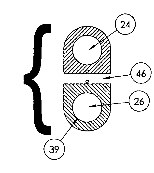
[0073]In the FIG. 5 embodiment, the outer walls 44 of the first and the second distal end tubes 14, 16 are separate (unattached) and independent from the transition point 36 to the distal ends 32, 34 (over the entire Arrow “B” longitudinal length in FIG. 5), as shown in FIG. 5b. The cross section of the first and the second distal end tubes 14, 16 (FIG. 5b) illustrates that the outer walls 44 of the first and the second distal end tubes 14, 16 over the Arrow “B” length, as well as the outer walls 39 of the first and the second lumens 24, 26, are rounded ...


PUM


Abstract

A multilumen catheter assembly is provided, which includes a unitary portion and at least two distal end tubes extending distally from the unitary portion. The unitary portion includes an exterior having a generally round or oval shape in cross section and includes at least two distal end tubes of generally circular (or other) cross sectional shape extending longitudinally therethrough. The catheter assembly may be made by extruding a unitary tube having internal longitudinally extending lumens (of circular or other shape), then splitting the tube on its distal end portion to form distal end tubes. The tubes are then ground and polished, the finished tubes retaining in combination the generally oval cross sectional shape of the unitary extrusion, or the finished tubes can each be finished to a circular, or other, cross sectional shape; or the finished tubes could include a combination of cross sectional shapes over its longitudinal length.

Description

RELATED APPLICATIONS[0001]The present application is a Continuation application of U.S. patent application Ser. No. 10 / 300,999, filed Nov. 21, 2002, U.S. Pat. No. 6,695,832, which is a Continuation-in-Part application of U.S. patent application Ser. No. 09 / 585,149, filed Jun. 1, 2000 U.S. Pat. No. 6,719,749, and which also claims the benefit of U.S. Provisional patent application Ser. No. 60 / 331,882, filed Nov. 21, 2001. Each of the above-referenced related applications are incorporated herein by this reference.FIELD OF THE INVENTION[0002]The present invention relates generally to multilumen catheter assemblies, and more particularly to multilumen catheter assemblies having a smooth, rounded unitary catheter portion for positioning at a vessel wall insertion site and independent, free floating catheter tubes for positioning within an area to be catheterized.BACKGROUND OF THE INVENTION[0003]Catheters for the introduction or removal of fluids may be located in various venous locations...

Claims


Application Information

Patent Timeline
Patent Type & Authority Patents(United States)
IPC IPC(8): A61M27/00A61M25/00A61M25/01A61M25/14A61M25/16A61M31/00
CPCA61M25/0009A61M25/0023A61M25/0029A61M25/0068A61M25/007A61M2025/0188A61M25/008A61M2025/0031A61M2025/0034A61M2025/0037A61M2025/0081A61M25/0071A61M25/0026
Inventor SCHON, DONALD A.MADISON, ANTHONY J.SCHWEIKERT, TIMOTHY M.
Owner MEDICAL COMPONENTS INC
Why Eureka
Try Eureka