
Femoral intramedullary rod system

Inactive Publication Date: 2006-03-28
COLE J DEAN
View PDF73 Cites 196 Cited by
  • Summary
  • Abstract
  • Description
  • Claims
  • Application Information

AI Technical Summary

Benefits of technology

[0014]In a further form of the present invention, a method of treating a bone fracture includes forming a first hole in a femur transverse to the medullary canal and introducing a transverse member through the first hole. The transverse member includes a through-hole that is positioned relative to the medullary canal of the femur, and is preferably aligned therewith. The method further includes forming a second hole intersecting the medullary canal and inserting an intramedullary nail into the medullary canal via the second hole. The nail passes through the through-hole of the transverse member. The nail may include an opening aligned with the transverse member to facilitate rigid assembly to the transverse member by positioning a pin coupled to the transverse member in the nail opening.
[0018]Still a further form of the present invention includes a technique for treating bone fractures with a nail that defines a longitudinal axis, an elongated opening extending therethrough, and a longitudinal passage intersecting the opening. A bone engaging member passes through the opening and a positioning device is provided that may be adjusted to change position of the bone engaging member along the longitudinal axis relative to the nail when the member is positioned through the nail opening. This device may be utilized to facilitate compression or distraction of a bone fracture.
[0023]Additionally or alternatively, still another object is to reduce the complexity and inventory costs associated with treating bone fractures.

Problems solved by technology

Overall, the femur is one of the longest and strongest bones in the human body; however, portions of the femur are extremely susceptible to fracture.
Any longitudinal, transverse, or rotational movement of one section of the fractured bone relative to the other can cause substantial delay in healing time or cause improper healing to occur.
However, such an arrangement injures the flesh and muscle surrounding the bones and a large number of pins driven through the bone tend to weaken its hard outer layer.
Plates also tend to stress the bone and are not always able to bear sufficient stress for many femoral fracture applications.
Further, bone beneath the plate does not always become as strong as it would in the absence of the plate.
While there have been a number of technological advances made within the area of intramedullary fixation of femoral fractures, several problem areas remain.
One such problem arises from the fact that most intramedullary fixation systems currently available are adapted to a specific type of femoral fracture, resulting in a large number of highly specialized configurations.
This has led to the disadvantageous consequence that hospitals and trauma centers have to keep a large inventory of incremental nail lengths with varying configurations and ancillary parts in order to accommodate a random and diverse incoming patient population.
Maintaining such a high level of inventory to handle all expected contingencies is not only complex, but is also very expensive.
Correspondingly, the possibility of error during selection and implantation of the fixation device by the surgeon is elevated.
Likewise, the inventory costs associated with varying methods of intramedullary fixation are drastically increased and, in the case of smaller medical facilities, may necessitate switching to a less costly and potentially less effective method of treating femoral fractures.
Another problem may result from intramedullary rod systems used to specifically treat fractures of the neck or head of the femur.
Unfortunately, this structural connection does not always prevent rotational or translational movement of the fixation member relative to the intramedullary rod in response to forces commonly resulting from the normal activity of a convalescing patient.
Additionally, the intramedullary rods used in these devices are typically specialized for use with this single fixation application and can not be used in other applications.
Therefore, the costs associated with maintaining increased levels of inventory are substantially increased.
Furthermore, if it is desired to vary the angle of the fixation member relative to the rod, substantial modifications must typically be made to either the fixation member or the rod member to accommodate for such an angular variation, again driving up inventory levels and associated inventory costs.
In still another problem area, on occasion, it is necessary to use transverse locking bone screws to lock the rod into position relative to the femur.
Unfortunately, the installation of locking nuts onto the ends of the locking screws requires additional surgical incisions and commonly causes soft tissue irritation.
In yet another problem area, when an intramedullary rod is inserted into the medullary canal and anchored to the femur by two or more bone screws, despite the best efforts of the surgeon, the fracture site may have either been over-compressed or over-distracted as a result of the insertion of the rod.
Unfortunately, with conventional intramedullary rods, it is virtually impossible to adjust the amount of distraction or compression without first removing one or more of the bone screws and manually distracting or compressing the fracture site.

Method used


Image

  • Femoral intramedullary rod system
  • Femoral intramedullary rod system
  • Femoral intramedullary rod system

Examples


Embodiment Construction

[0060]For the purposes of promoting an understanding of the principles of the invention, reference will now be made to the embodiments illustrated in the drawings and specific language will be used to describe the same. It will nevertheless be understood that no limitation of the scope of the invention is thereby intended, any alterations and further modifications in the illustrated embodiments, and any further applications of the principles of the invention as illustrated therein being contemplated as would normally occur to one skilled in the art to which the invention relates.

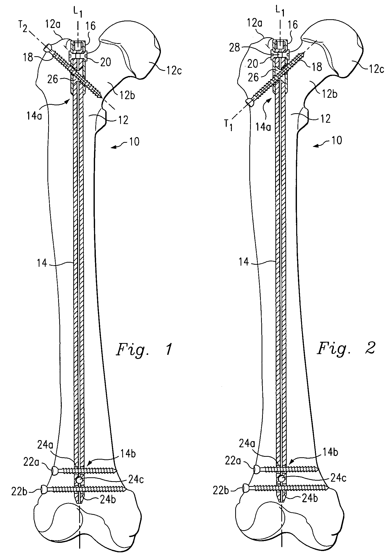
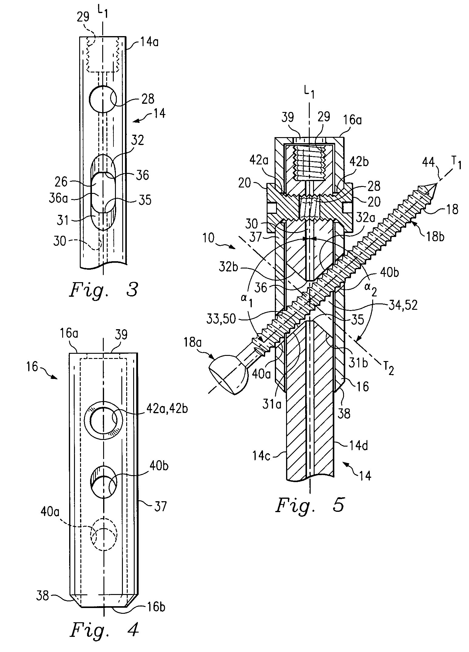
[0061]FIGS. 1–2 depict intramedullary system 10 according to one embodiment of the present invention. System 10 is shown implanted in femur 12 and includes an elongated intramedullary rod or nail 14, sleeve 16 and bone engaging member 18. System 10 also includes fasteners 20 and locking bone screws 22a, 22b. FIG. 1 illustrates system 10 as used in a first locking configuration with bone engaging member 18 pl...


PUM


Abstract

A femoral intramedullary rod system capable of treating a variety of femoral bone fractures using a uniform intramedullary rod design. The system generally comprising an intramedullary rod defining an opening having an upper surface and a transverse member including a bone engaging portion and a connection portion defining a thru-hole with the nail sized to pass therethrough. A pin is selectively coupled to the transverse member to rigidly assemble the transverse member to the nail when the nail is passed through the thru-hole and the pin is received within the opening. In an alternative design, an epiphyseal stabilizer is joined to the nail by a locking member.

Description

[0001]The present application is a continuation-in-part of U.S. patent application Ser. No. 09 / 619,189 filed Jul. 19, 2000 now U.S. Pat. No. 6,402,753 and claims the priority thereof, which is a divisional of U.S. patent application Ser. No. 09 / 329,688 filed Jun. 10, 1999, now U.S. Pat. No. 6,221,074, each of the above are hereby incorporated by reference.FIELD OF THE INVENTION[0002]The present invention is directed to techniques for treating bone fractures. Specifically, but not exclusively, the invention relates to a system for treating a variety of typical femoral fractures using a uniform intramedullary rod design.BACKGROUND OF THE INVENTION[0003]The femur generally comprises an elongated shaft extending from the hip to the knee. The proximal end of the femoral shaft includes a neck segment connected to a head portion. The head portion fits into a concavity of the hip bone to form a ball and socket joint at the hip. The distal end of the femoral shaft engages the upper end of th...

Claims


Application Information

Patent Timeline
IPC IPC(8): A61B17/16A61B17/78
CPCA61B17/164A61B17/72A61B17/7216A61B17/7241A61B17/725A61B17/744A61B17/8685A61B17/7225
Inventor COLE, J. DEAN
Owner COLE J DEAN
Learn More