
Textured surface having undercut micro recesses in a surface

a micro recess and surface technology, applied in the field of textured surfaces, can solve the problems of voids formed by the spheres not being sufficient for long-term nourishment, affecting the usefulness of implanted devices using such surfaces, and affecting the long-term use of implanted devices. , to achieve the effect of reducing micro-motion

Inactive Publication Date: 2006-03-28
TECMET
View PDF142 Cites 256 Cited by
  • Summary
  • Abstract
  • Description
  • Claims
  • Application Information

AI Technical Summary

Benefits of technology

The method achieves stable bone adhesion and implant integration by creating a surface with undercut micro recesses that promote bone ingrowth, reduces micro-motion, and maintains the metallurgical integrity of the implant material, leading to improved long-term interconnection and reduced risk of implant failure.

Problems solved by technology

While an improvement over untreated metal, questions have arisen over the longevity of usefulness of the implanted devices utilizing such surfaces.
It is questionable whether there is substantial genuine adhesion.
It is believed that the voids formed by the spheres are not sufficient for long-term nourishment of ingrowing tissue and / or bone.
Further, there have been failures of prosthetics treated in this manner because of the fusing process adversely affecting metallurgical properties. of the implant material, and because of difficulties in removing manufacturing contaminants, such as cutting oils, from the fused sphere network.
Still further, the original datum surface, which can be accurately determined, is lost by the application of the coating spheres.
The processes therein described have been found lacking in precise control over the degree and extent of roughness or texturing.

Method used


Image

  • Textured surface having undercut micro recesses in a surface
  • Textured surface having undercut micro recesses in a surface
  • Textured surface having undercut micro recesses in a surface

Examples


Embodiment Construction

[0009]A preferred embodiment of the invention is a textured surface which is adapted to interlock with an adjacent body and method of producing a textured surface.

[0010]A further embodiment is to provide a texture having an undercut micro recesses in a surface of a body and method of producing a textured surface.

[0011]A still further embodiment provides recesses in a desired pattern which is measurable and predictable, and which can be duplicated and repeated precisely in any selected number of surfaces and method of producing a textured surface.

[0012]A still further embodiment is a surgical implant device wherein the material of the device retains its metallurgical properties throughout production and method of producing a textured surface.

[0013]A still further embodiment is a surgical implant, with a textured surface that promotes the in-growth of tissue and / or bone to securely interconnect the implant and the tissue and / or bone and method of producing a textured surface.

[0014]A s...


PUM

PropertyMeasurementUnit
temperatureaaaaaaaaaa
wavelengthaaaaaaaaaa

Abstract

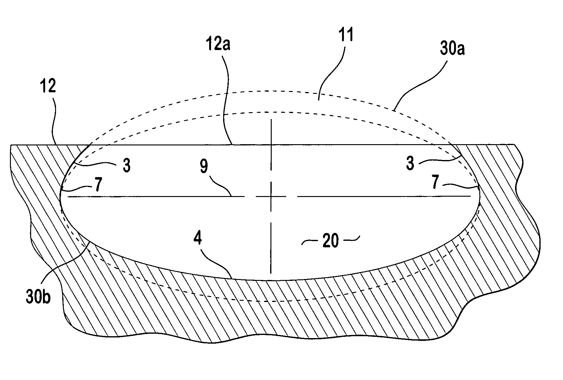
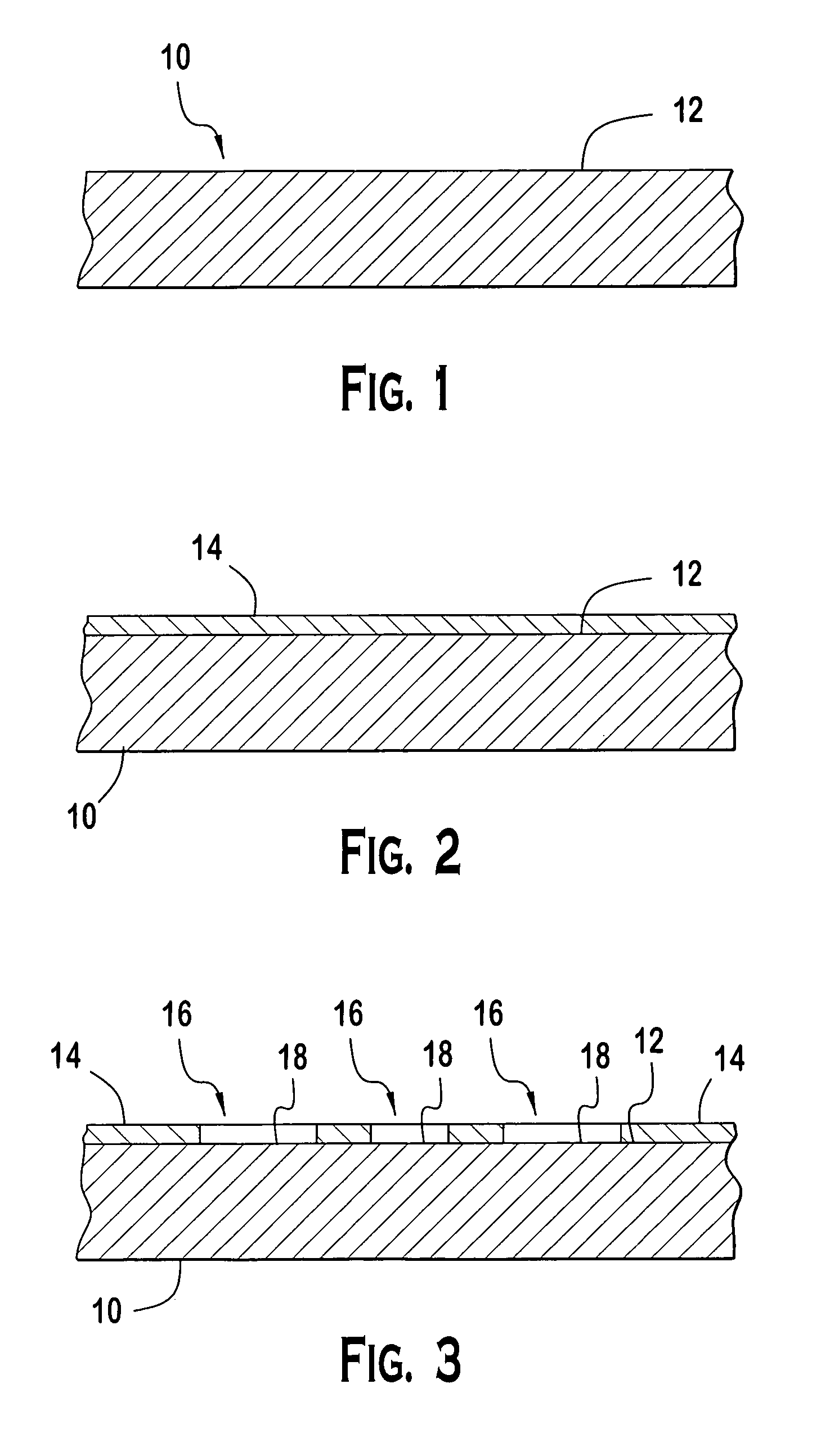
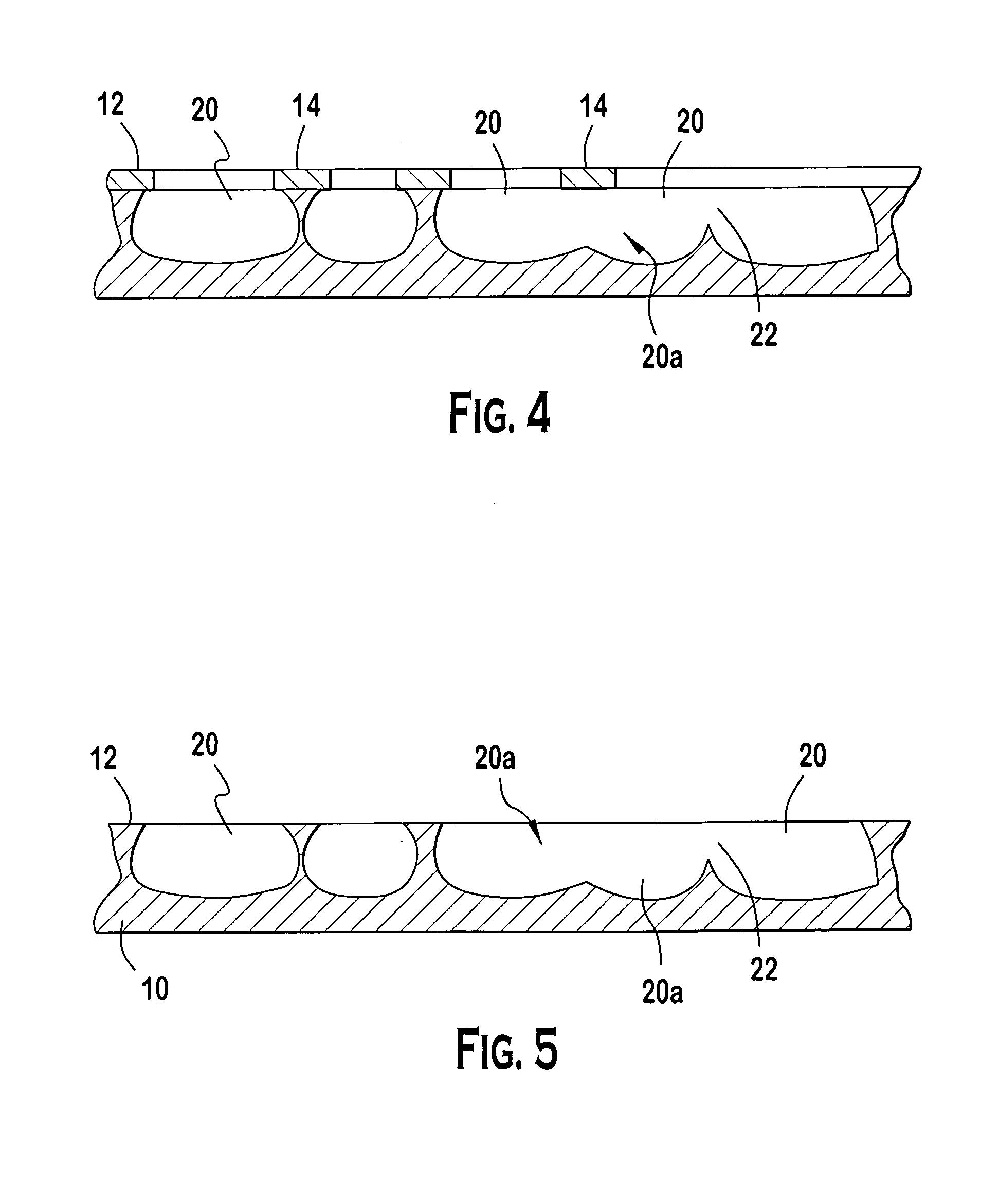
Textured surface having micro recesses such that the outer surface overhangs the micro recesses. Embodiments of the textured surface include sharp edges for promoting bone deposition and growth within the micro recesses, protrusions of varying depth from the surface that include overhangs, and micro recesses that are at least partially defined by complex ellipsoids.

Description

CROSS-REFERENCE TO RELATED APPLICATIONS[0001]This application is a continuation-in part of U.S. application Ser. No. 09 / 976,722 filed Oct. 12, 2001, now U.S. Pat. No. 6,599,322 which claims the benefit of U.S. Provisional Application No. 60 / 264,084 filed, Jan. 25, 2001, and U.S. Provisional Application No. 60 / 309,923, filed Aug. 3, 2001. This application is also a continuation-in-part of U.S. application Ser. No. 10 / 021,616, filed Dec. 12, 2001, now U.S. Pat. No. 6,620,332 which claims benefit of U.S. Provisional Application 60 / 291,022, filed May 15, 2001. This application, furthermore, claims the benefit of priority of U.S. Provisional Application No. 60 / 340,286, filed Dec. 12, 2001, U.S. Provisional Application No. 60 / 356,459, filed Feb. 11, 2002, U.S. Provisional Application No. 60 / 388,033, filed Jun. 12, 2002, and U.S. Provisional Application No. 60 / 391,957, filed Jun. 25, 2002.BACKGROUND OF THE INVENTION[0002]1. Field of the Invention[0003]The invention relates to the productio...

Claims


Application Information

Patent Timeline
Patent Type & Authority Patents(United States)
IPC IPC(8): A61F2/28A61F2/02A61C8/00A61B17/80A61F2/00A61F2/30A61F2/32A61F2/34A61F2/36A61F2/38A61F2/44A61L27/00B32B3/30C03C15/00C04B41/91C23F1/02
CPCA61B17/8085C23F1/02A61F2/30767A61F2/30771A61F2/446B32B3/30A61C2008/0046A61F2/2803A61F2/32A61F2/34A61F2/36A61F2/3662A61F2/3859A61F2002/30149A61F2002/30153A61F2002/3021A61F2002/30217A61F2002/30253A61F2002/30535A61F2002/30777A61F2002/3078A61F2002/30785A61F2002/30787A61F2002/30838A61F2002/30874A61F2002/30879A61F2002/30883A61F2002/30892A61F2002/30925A61F2002/30927A61F2002/30952A61F2002/3097A61F2002/3611A61F2002/3625A61F2002/3631A61F2002/365A61F2230/0017A61F2230/0019A61F2230/0067A61F2230/0076A61F2250/0058A61F2310/00017A61F2310/00023A61F2310/00029A61F2310/00089A61F2310/00131A61F2310/00179A61F2310/00269A61F2310/00329B23K2203/14A61C8/0012A61F2002/30873B23K2103/14
Inventor AMRICH, MARKROLFE, JONATHAN L.BUTURLIA, JOSEPHLYNCH, ROBERT F.
Owner TECMET
Learn More