Gas cabinet including integrated effluent scrubber

a scrubber and effluent technology, applied in the field of gas cabinets, can solve the problems of substantial capital equipment and operating costs, and achieve the effect of minimizing vent gas abatement problems

Inactive Publication Date: 2006-03-28
ADVANCED TECH MATERIALS INC
View PDF20 Cites 22 Cited by
  • Summary
  • Abstract
  • Description
  • Claims
  • Application Information

AI Technical Summary

Benefits of technology

[0007]The present invention relates to a gas cabinet useful in semiconductor manufacturing operations, which is constructed and operated to effect local scrubbing of gas in the gas cabinet, thereby minimizing vent gas abatement issues.
[0016]In another aspect, the invention relates to a gas delivery process wherein process gas from a gas supply vessel is flowed through flow circuitry in a gas cabinet and dispensed from the gas cabinet, and the flow circuitry subsequent to process gas dispensing is purged with a purge gas to remove residual process gas from the flow circuitry and yield a purge effluent including the purge gas and residual process gas from the flow circuitry. The process includes contacting the purge effluent with a dry scrubbing medium that is effective to remove the process gas from the purge effluent and yield a process gas-depleted purge effluent, and pumping the process gas-depleted purge effluent out of the gas cabinet with a venturi pump.

Problems solved by technology

In the use of such gas sources, an exhaust scrubber for treatment of the vent gas from the gas cabinet containing the gas source entails substantial capital equipment and operating costs.
The alternative of piping the vent gas from the gas cabinet to the ducting of the house exhaust system of the semiconductor manufacturing facility avoids such expenditures, but the purging of the gas panel flow circuitry incident to changeovers of gas source vessels can cause false alarms by toxic gas monitor alarms that are arranged to detect leakage from gas source vessels and / or gas flow circuitry in the exhaust stream.

Method used


Image

  • Gas cabinet including integrated effluent scrubber
  • Gas cabinet including integrated effluent scrubber
  • Gas cabinet including integrated effluent scrubber

Examples


Embodiment Construction

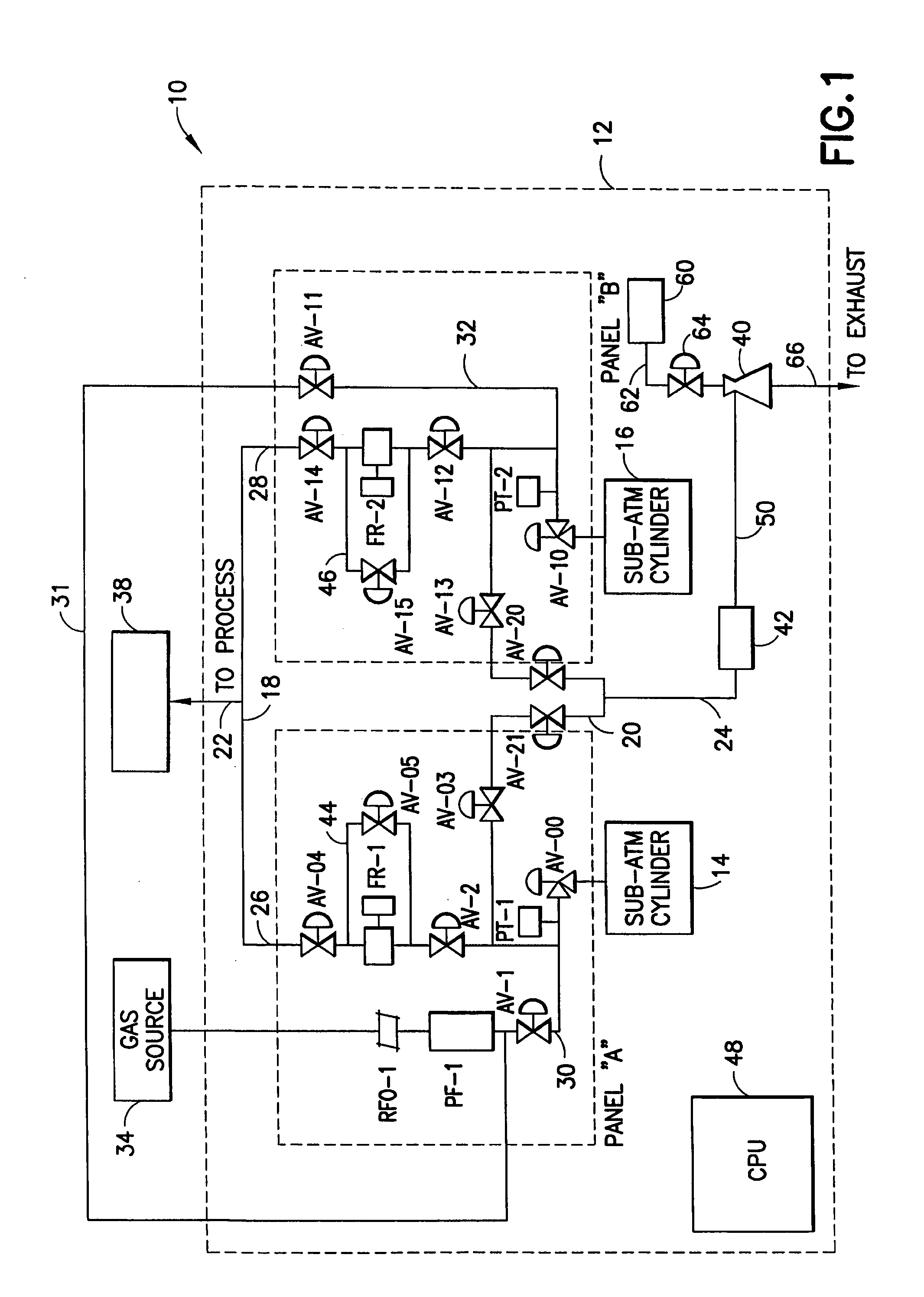
[0020]The present invention relates to gas cabinets useful in semiconductor manufacturing operations, which are used for dispensing of a process gas to the semiconductor manufacturing facility, e.g., to a specific process tool therein, such as an ion implanter, chemical vapor deposition chamber, etc.

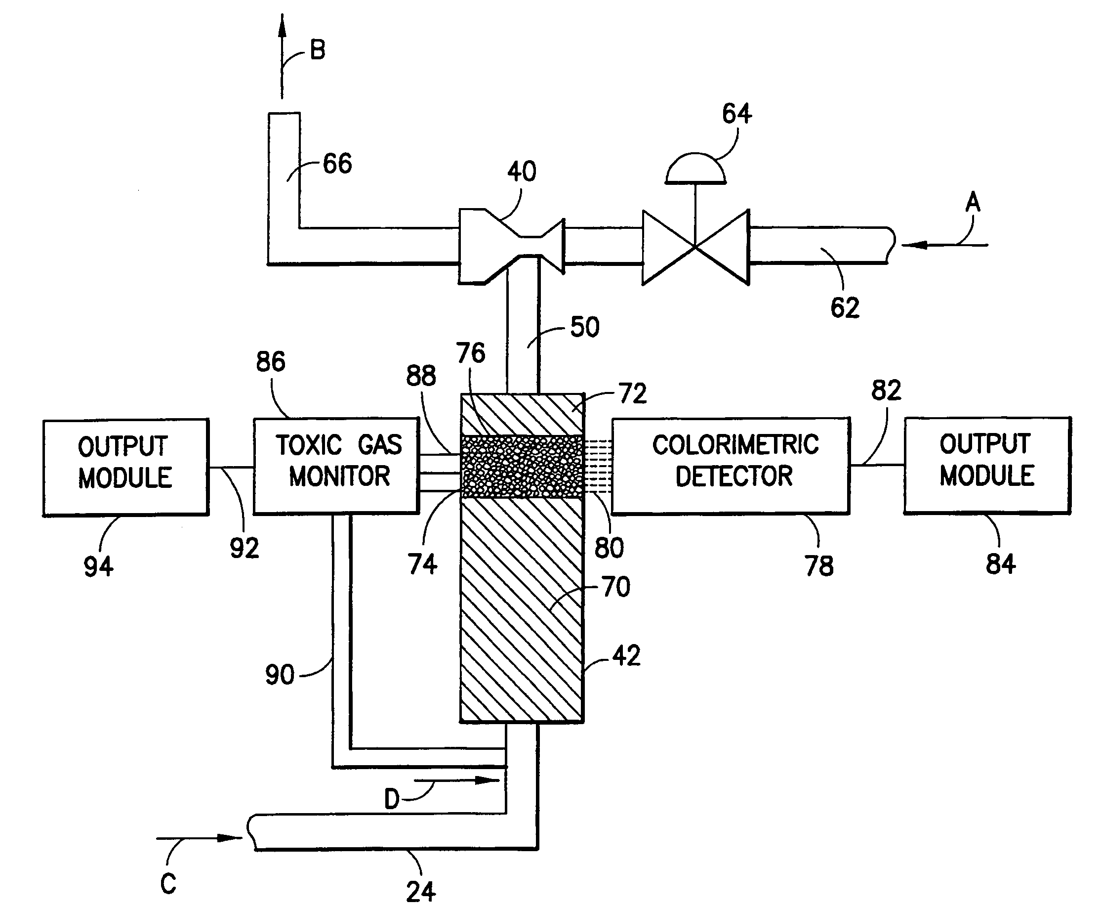
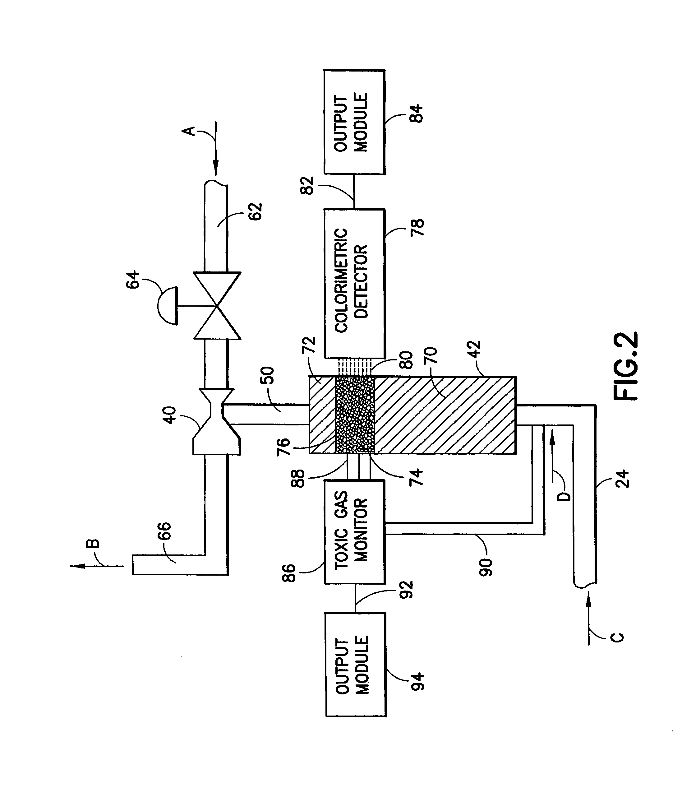
[0021]In accordance with the invention, a purge gas scrubber is integrated with the gas flow circuitry in a gas cabinet. Purge gas is flowed through the flow circuitry in the gas cabinet subsequent to on-stream dispensing of process gas through such flow circuitry. The purge gas thereby displaces and entrains the residual process gas in the flow circuitry to form a purge effluent. The purge effluent is flowed through a dry scrubber unit including a scrubber medium selectively sorptive for the process gas, to sorptively remove the process gas species from the purge effluent. The resultant process gas-depleted purge effluent then may be vented from the semiconductor manufacturing facility,...


PUM

PropertyMeasurementUnit
pressureaaaaaaaaaa
pressureaaaaaaaaaa
pressuresaaaaaaaaaa

Abstract

A gas cabinet assembly for dispensing of gas to a process facility such as a semiconductor manufacturing tool. A purge gas dry scrubber is integrated with the gas flow circuitry and a venturi pump in the gas cabinet. Purge gas is flowed through the flow circuitry in the gas cabinet subsequent to on-stream dispensing of process gas through such flow circuitry, and forms a purge effluent including the residual process gas. The purge effluent is flowed through a dry scrubber unit to sorptively remove the process gas species from the purge effluent. The resultant process gas-depleted purge effluent is vented from the gas cabinet, e.g., into the ducting of the house exhaust system of the process facility. Monitoring of the relative depletion of the dry scrubbing medium in the dry scrubber may be carried out with endpoint detection, e.g., using colorimetric change techniques, toxic gas monitor devices, or PLC / CPU arrangements.

Description

BACKGROUND OF THE INVENTION[0001]1. Field of the Invention[0002]This invention relates to a gas cabinet useful in semiconductor manufacturing operations, and more specifically to a gas cabinet including an integrated effluent scrubber.[0003]2. Description of the Related Art[0004]In semiconductor manufacturing operations, highly efficient gas sources have come into use that are employed in gas cabinets containing the gas source vessels and associated flow circuitry, as well as associated monitoring and control componentry. Such gas sources include the sources described in U.S. Pat. No. 5,518,528 issued May 21, 1996 to Glenn M. Tom, et al., U.S. Pat. No. 6,089,027 issued Jul. 18, 2000 to Luping Wang et al. and U.S. Pat. No. 6,101,816 issued Aug. 15, 2000 to Luping Wang et al. These gas sources are commercially available from ATMI, Inc. (Danbury, Conn., USA) under the trademarks SAGE and VAC.[0005]In the use of such gas sources, an exhaust scrubber for treatment of the vent gas from th...

Claims


Application Information

Patent Timeline
Patent Type & Authority Patents(United States)
IPC IPC(8): B01D53/04B01D53/02
CPCB01D53/0446B01D53/0454B01D2253/104B01D2253/11B01D2253/202B01D2259/4525B01D2257/93B01D2258/0216B01D2259/40009B01D2259/402B01D2257/706
Inventor WODJENSKI, MICHAEL J.ARNO, JOSE I.
Owner ADVANCED TECH MATERIALS INC
Why Eureka
Try Eureka