Heater

a heater and cartridge technology, applied in the field of heaters, can solve the problems of accelerating the deterioration of the insulation resistance of the electrically insulating material, the breakage of the heating element, and the local temperature is extraordinarily high, so as to achieve the effect of facilitating maintenance of electrical insulation

Inactive Publication Date: 2006-03-28
SANYO NETABUINDS
View PDF8 Cites 29 Cited by
  • Summary
  • Abstract
  • Description
  • Claims
  • Application Information

AI Technical Summary

Benefits of technology

[0008]According to the present invention, in a heater in which an electrically insulating material constituted by an oxide is filled between a heating element made of metal containing chromium and aluminum and a cover for sealing the heating element and in which a lead wire of the heating element extends through a portion serving as an electrical insulator of the cover, an oxide film including aluminum oxide is formed on the surface of the heating element, so that the surface of the heating element is electrically insulated by the aluminum oxide film, and the oxide film suppresses the generation of chromium vapors, etc., from the heating element in its heated state. This may suppress the phenomenon known as blackening of the electrically insulating material that may be caused by conductive chromium or like that evaporates and is released from the heating element and is dispersed into the electrically insulating material. In addition, the amount of oxygen that is removed from the oxide electrically insulating material between the heating element and cover by chromium vapors or the like may be suppressed. As a result, deterioration of the insulation resistance of the electrically insulating material is suppressed.
[0009]Further, the cover has good thermal conductivity because the portions of the cover other than the electrical insulator are constituted by a metal including nickel and chromium; the generation of nickel vapors and chromium vapors due to temperature increases in the metal portion of the cover is suppressed when heat is generated by the heating element, because an oxide film is formed on the surface of the metal portion of the cover. This may suppress the phenomenon known as blackening of the electrically insulating material that may be caused by conductive chromium and nickel that evaporates and is released from the metal portion of the cover and is dispersed into the electrically insulating material. In addition, the amount of oxygen that is removed from the oxide electrically insulating material filled between the heating element and the cover by nickel vapor and chromium vapor may be suppressed. As a result, deterioration of the insulation resistance of the electrically insulating material is suppressed.
[0010]Further, the electrically insulating oxide film formed on the surface of the heating element enables the heating element to be wound at a small pitch, if the heating element is formed as a spirally wound wire. As a result, if the resistance of the heating element is maintained at a predetermined value, the heating element may have a larger diameter and may accordingly have greater length, so that breakage of the heating element can be prevented.
[0011]Further, because the amount of heat generated by the heating element per unit of surface area of the same is reduced by increasing the diameter of the heating element, heat will be more easily transferred from the heating element to the cover; thus, breakage of the heating element can be suppressed, because there is a small temperature increase at the core of the heating element relative to the temperature at its surface.
[0013]Further, if the portion of the cover other than the portion comprising an electrically insulating body is a tubular portion consisting of metal including nickel and chromium serving as a sheath, it is easy to fill electrically insulating material between the heating element and the tubular metal portion sheath when the oxide film is formed on the surface of the tubular metal portion.
[0014]Furthermore, if the tubular metal portion that serves as a sheath has a cylindrical configuration, it is even easier to maintain electrical insulation between the heating element and the tubular metal portion sheath by filling an electrically insulating material between the heating element and the cylindrical metal portion.

Problems solved by technology

Thus, a reduction reaction of the electrically insulating material and a phenomenon known as blackening of the electrically insulating material will result, because of the dispersal of conductive chromium, chromium oxide, nickel, and iron, which evaporate and are released from the heating element and the metal portion of the cover in the electrically insulating material, thereby accelerating the deterioration of the insulation resistance of the electrically insulating material.
As a result, an extraordinarily large leakage current sometimes flows from the heating element to some locations of the metal portion of the cover via the electrically insulating material when the sheathed heater or cartridge heater is being used, and a large amount of Joule heat is locally generated at the heating element, thereby developing an extraordinarily high local temperature, which cause problems of breakage occuring in the heating element that has become thin due to release of the chromium, nickel, and iron components and the cover may melt or break.

Method used


Image

  • Heater
  • Heater
  • Heater

Examples


first embodiment

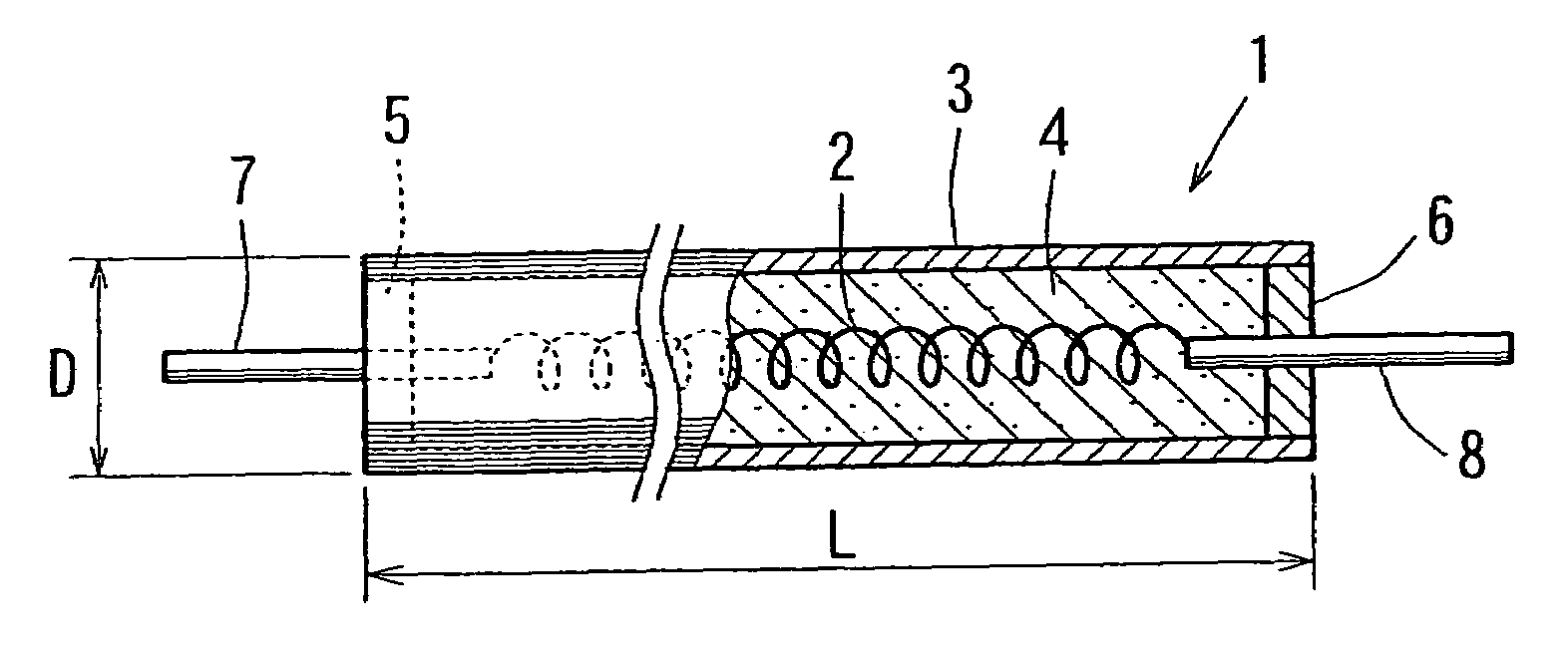
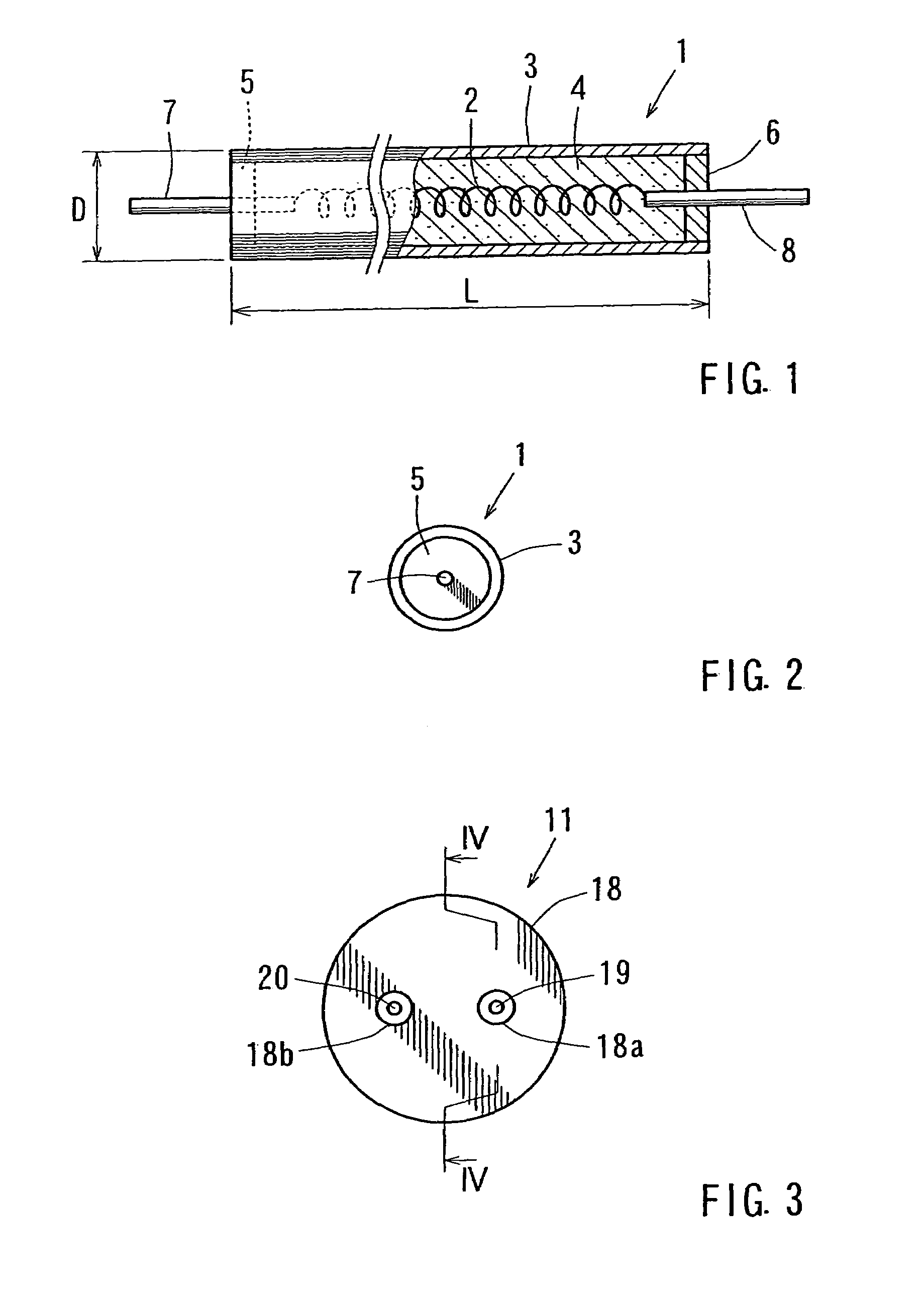
[0024]FIG. 1 is a partially cut-away front view of a sheathed heater according to the invention, and FIG. 2 shows a left side view of the heater shown in FIG. 1.

[0025]In FIG. 1, a sheathed heater 1 includes a heating element 2 made of metal containing chromium and aluminum in the form of a wire having a spiral-shaped configuration; pipe 3 is made of metal containing nickel and chromium and serves as a sheath for covering the heating element 2; an electrically insulating material 4 for electrical insulating is disposed between the heating element 2 and the pipe 3; a first lead wire 7 is connected to the left end of the heating element 2 as viewed in the figure; a second lead wire 8 is connected to the right end of the heating element 2 as viewed in the figure; a first lead glass 5 seals the left end of the pipe 3 as viewed in the figure; and a second lead glass 6 seals the right end of the pipe 3 as viewed in the figure. The pipe 3 and the first and second lead glass portions 5 and 6...

second embodiment

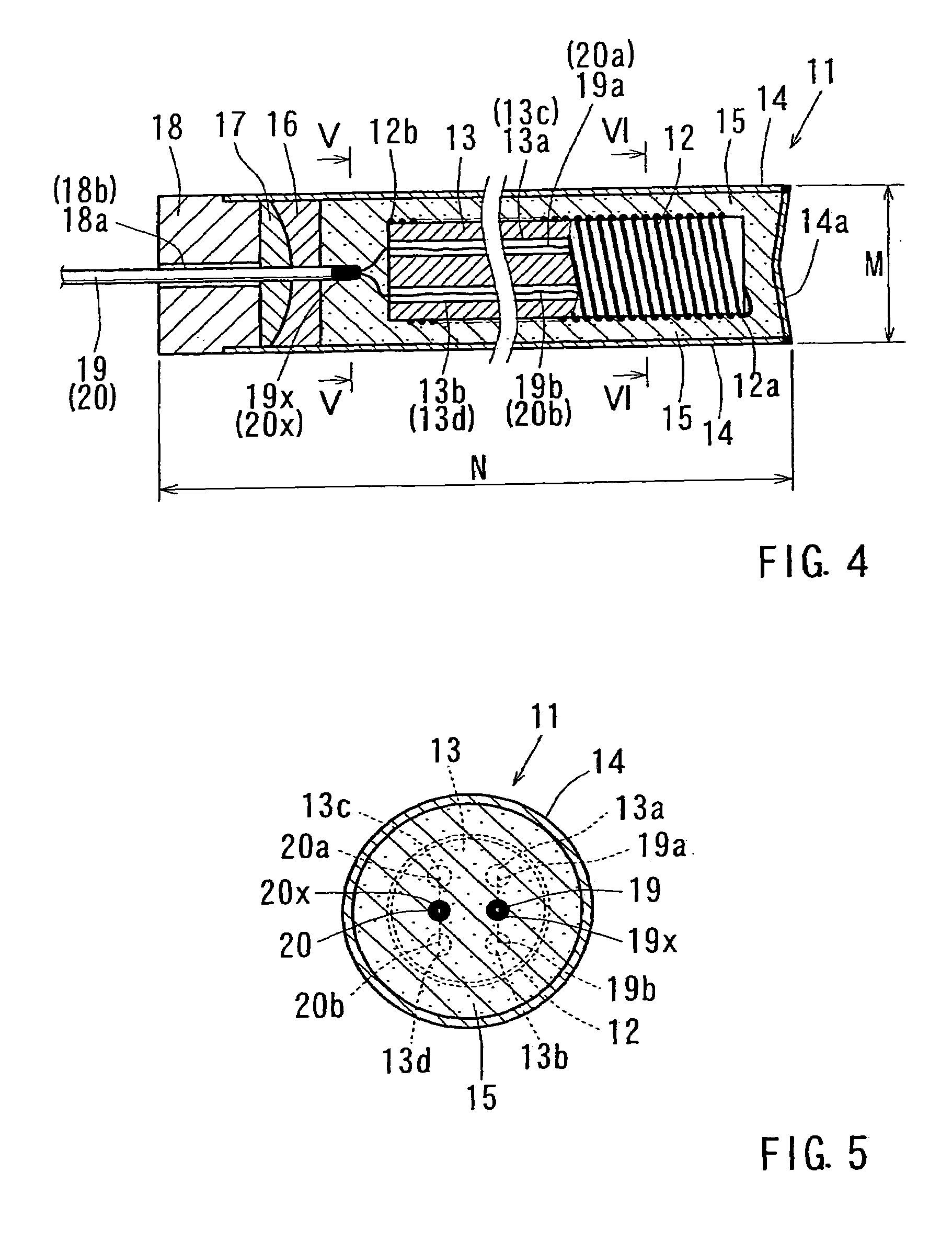
[0041]FIG. 3 is an enlarged view on the side of lead wires of a cartridge heater according to the present invention; FIG. 4 is a slightly reduced cross-sectional view of the structure taken along line IV—IV in FIG. 3; FIG. 5 is an enlarged cross-sectional view of the structure taken along line V—V in FIG. 4; and FIG. 6 is an enlarged cross-sectional view of the structure taken along line VI—VI in FIG. 4.

[0042]As shown in FIG. 3, in a cartridge heater 11, a first lead wire 19 extends through a through hole 18a of an entrance insulator 18, and a second lead wire 20 extends through a through hole 18b of the entrance insulator 18. The first lead wire 19 and second lead wire 20 are rod-shaped members made of metal and serve as lead wires for a heating element 12 that will be described below.

[0043]As shown in FIG. 4, the cartridge heater 11 is formed by filling a pipe 14 made of metal and serving as a sheath (with a welded bottom plate 14a) with an electrically insulating material 15; a c...


PUM


Abstract

In a heater in which an electrically insulating material (4) including an oxide is filled between a heating element (2) made of metal including chromium and aluminum and a cover (3, 5, 6) for sealing the heating element (2), and in which a lead wire (7, 8) of the heating element (2) extends through a portion (5, 6) of an electrical insulator of the cover (3, 5, 6) in order to enable the heater to be used at temperatures higher than the prior art, an oxide film including aluminum oxide is formed on the surface of the heating element (2). The portion of the cover (3, 5, 6) excluding the portion (5, 6) serving as an electrical insulator is a metal pipe (3) that serves as a sheath and includes nickel and chromium, and an oxide film is formed on the surface of the metal pipe (3). Therefore, the heater can be used in dies for plastic forming or the like.

Description

TECHNICAL FIELD[0001]The present invention relates to sheathed heaters, cartridge heaters, and the like and, more particularly, to techniques for enabling sheathed heaters, cartridge heaters, and the like to be used at temperatures higher than temperatures that are conventionally available.BACKGROUND ART[0002]Sheathed heaters and cartridge heaters have been conventionally used. These heaters include a heating element in the form of a metal wire, a cover for sealing the heating element, and an electrical insulating material constituted by an oxide, e.g., magnesium oxide, that is filled between the heating element and the cover. The cover is composed of a metal portion and an electrical insulator portion through which lead wires of the heating element extend. Joule heat is generated at the heating element by energizing the heating element via the lead wires.[0003]Because nickel, chromium, and iron are normally used as part of the composition of the heating element and the metal portio...

Claims


Application Information

Patent Timeline
Patent Type & Authority Patents(United States)
IPC IPC(8): H05B3/44H05B3/48
CPCH05B3/48
Inventor OKUDA, KATSUHIKO
Owner SANYO NETABUINDS
Why Eureka
Try Eureka