
Subscriber interface protection circuit

a protection circuit and subscriber technology, applied in the field of circuits, can solve the problems of increasing the problem of the protection of interface circuits, especially in the direction of emergency protection arrangements for limiting excess voltage/current, electrical equipment,

Inactive Publication Date: 2006-03-28
STMICROELECTRONICS SRL
View PDF10 Cites 37 Cited by
  • Summary
  • Abstract
  • Description
  • Claims
  • Application Information

AI Technical Summary

Benefits of technology

"The present invention provides a monolithic protection circuit that can short-circuit between each conductor of a line and a ground when the voltage on a conductor exceeds a determined positive threshold or becomes lower than a predetermined negative threshold. The circuit can also short-circuit when the current in a conductor exceeds a determined threshold. The circuit is manufacturable by technologies compatible with power integrated circuits developed by the applicant and is reliable in operation. The circuit requires a very low current to be started and minimizes the on-state voltage drop. The circuit includes a monolithic component made in a substrate of the first conductivity type divided into wells separated by isolating walls, the lower surfaces of which are coated with insulating layers, the lower surface being uniformly coated with a metallization. The circuit also includes a diode in the form of a P-type region itself formed in an N-type region, the diode being connected to the anode-gate thyristor. The technical effects of the present invention are that it provides a reliable and efficient protection against line overvoltages and minimizes the on-state voltage drop."

Problems solved by technology

Telephone circuits connected to lines are particularly likely to be disturbed by overvoltages such as lightning discharges or accidental connections to lines of the electric power network.
Further, the problem of the protection of interface circuits becomes more and more acute as these interface circuits are formed of more and more integrated circuits of smaller and smaller dimensions and accordingly, more and more sensitive to overvoltages.

Method used


Image

  • Subscriber interface protection circuit
  • Subscriber interface protection circuit
  • Subscriber interface protection circuit

Examples


Embodiment Construction

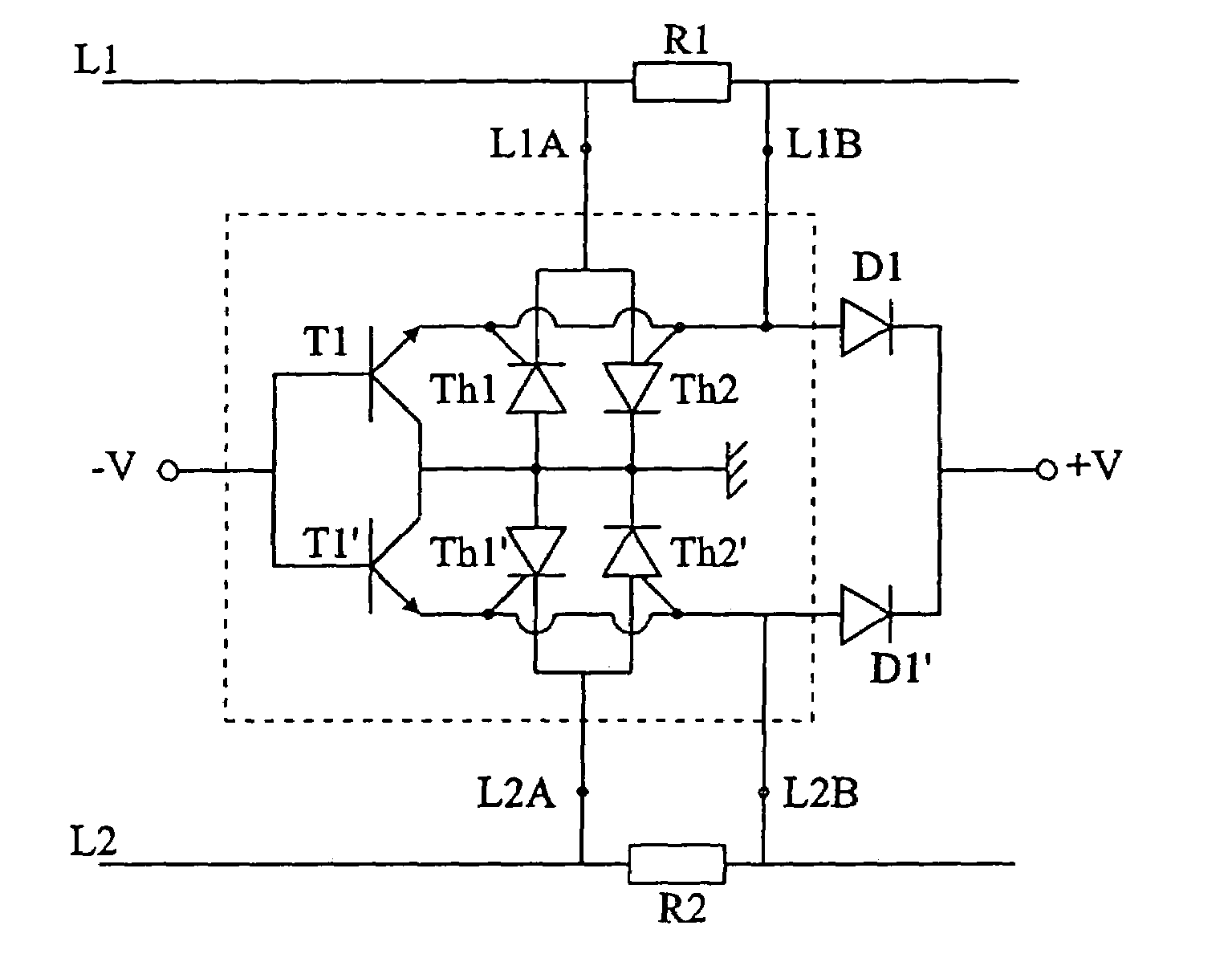
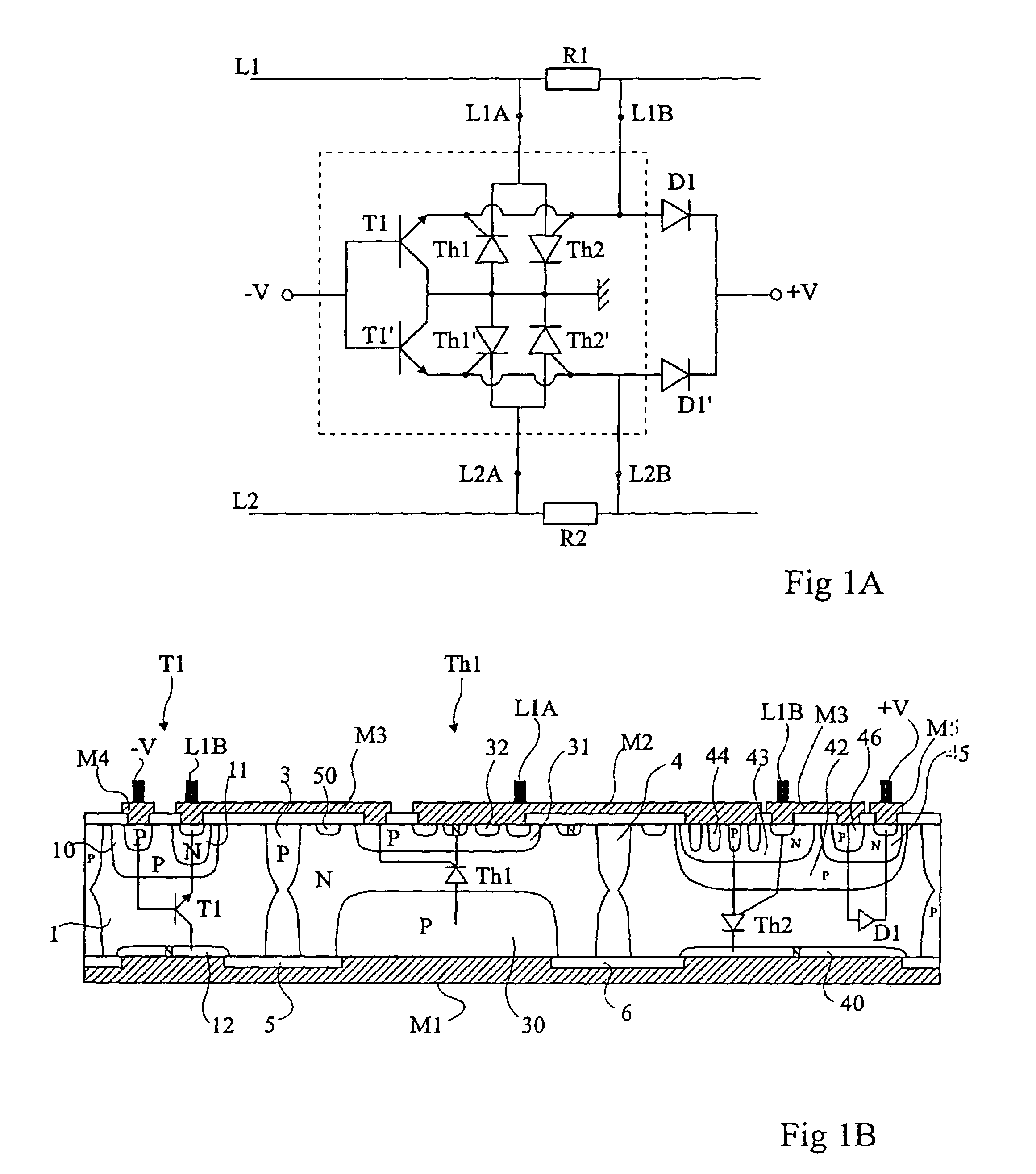
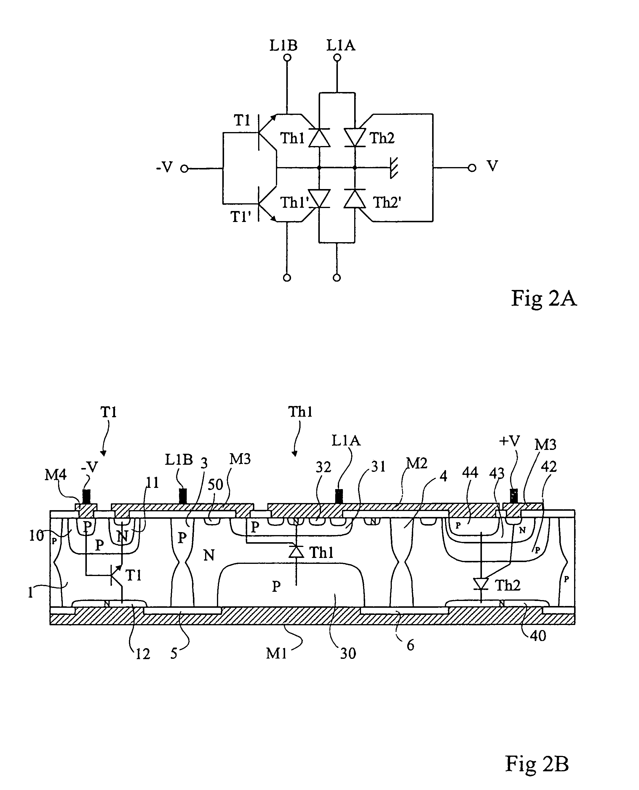
[0024]FIG. 1A shows a circuit that protects against overvoltages and overcurrents on a telephone line L1–L2. Each of the conductors of the telephone line includes a series resistor, respectively R1, R2, enabling to detect overcurrents. The terminals of resistor R1 which form first input terminals of the circuit according to the present invention will be called L1A and L1B and the terminals of resistor R2 which form second input terminals of the circuit will be called L2A and L2B. Between terminal L1A and a reference potential, currently the ground, two antiparallel thyristors, that is, a cathode-gate thyristor Th1 and an anode-gate thyristor Th2, are arranged. The anode of thyristor Th1 and the cathode of thyristor Th2 are grounded, and the cathode of thyristor Th1 and the anode of thyristor Th2 are connected to terminal L1A. The gate of the cathode-gate thyristor is connected to a negative voltage source −V via an NPN-type amplifier transistor T1. The gate of the anode-gate thyrist...


PUM


Abstract

The present invention relates to a monolithic component of protection of a line against overvoltages than a determined positive threshold or smaller than a determined negative threshold, including in antiparallel a cathode-gate thyristor (Th1) and an anode-gate thyristor (Th2), the gate of the cathode-gate thyristor being connected to a negative threshold voltage (−V) via a gate current amplification transistor (T1), the gate of the anode-gate thyristor being connected to a positive threshold voltage (+V). The monolithic component is made in a substrate divided into wells separated by isolating walls (3, 4), the smaller surfaces of which are coated with insulating layers (5, 6), the smaller surface of the substrate being uniformly coated with a metallization (M1).

Description

BACKGROUND OF THE INVENTION[0001]1. Field of the Invention[0002]The present invention relates to circuits that protect against overvoltages, which circuits can be used in particular for subscriber line interface circuits (SLIC).[0003]2. Discussion of the Related Art[0004]Telephone circuits connected to lines are particularly likely to be disturbed by overvoltages such as lightning discharges or accidental connections to lines of the electric power network. Further, the problem of the protection of interface circuits becomes more and more acute as these interface circuits are formed of more and more integrated circuits of smaller and smaller dimensions and accordingly, more and more sensitive to overvoltages.[0005]The applicant has been studying SLIC protection circuits for many years and has already devised several novel circuits, monolithically implementable, which are described, in particular, in U.S. Pat. Nos. 5,274,524, 5,243,488, 5,696,391 and 5,684,322, and in European patent ...

Claims


Application Information

Patent Timeline
Patent Type & Authority Patents(United States)
IPC IPC(8): H01L29/74H01L23/62H01L21/822H01L27/02H01L27/06H02H9/04
CPCH02H9/043H01L27/0248
Inventor BALLON, CHRISTIAN
Owner STMICROELECTRONICS SRL
Learn More