Position measuring device

a technology of positioning and measuring device, which is applied in the direction of converting sensor output, instruments, material analysis, etc., can solve the problems of large problems, inability to directly use laser interferometers on the optical imaging system of the wafer stepper, and noise in positioning and reproducibility, so as to prevent incorrect measurements

Inactive Publication Date: 2006-03-28
DR JOHANNES HEIDENHAIN GMBH
View PDF13 Cites 48 Cited by
  • Summary
  • Abstract
  • Description
  • Claims
  • Application Information

AI Technical Summary

Benefits of technology

[0010]It is therefore an object of the present invention to disclose a high-resolution position measuring device, which is insensitive to tilting

Problems solved by technology

In this connection the effects of disturbances in the air are detrimental, which in the end lead to positional noise and problems in regard to reproducibility.
However, often the mounting of laser interferometers directly on the optical imaging system of the wafer stepper is not possible and not desired for reasons of space limitation and because of the thermal dissipation, so that it is necessary to fasten all parts of the laser interferometer on a special frame made of Invar or Zerodur.
The changing of the lasers and the recalibration of the laser interferometer also cause considerable problems.
The high cost of the six to

Method used


Image

  • Position measuring device
  • Position measuring device
  • Position measuring device

Examples


Embodiment Construction

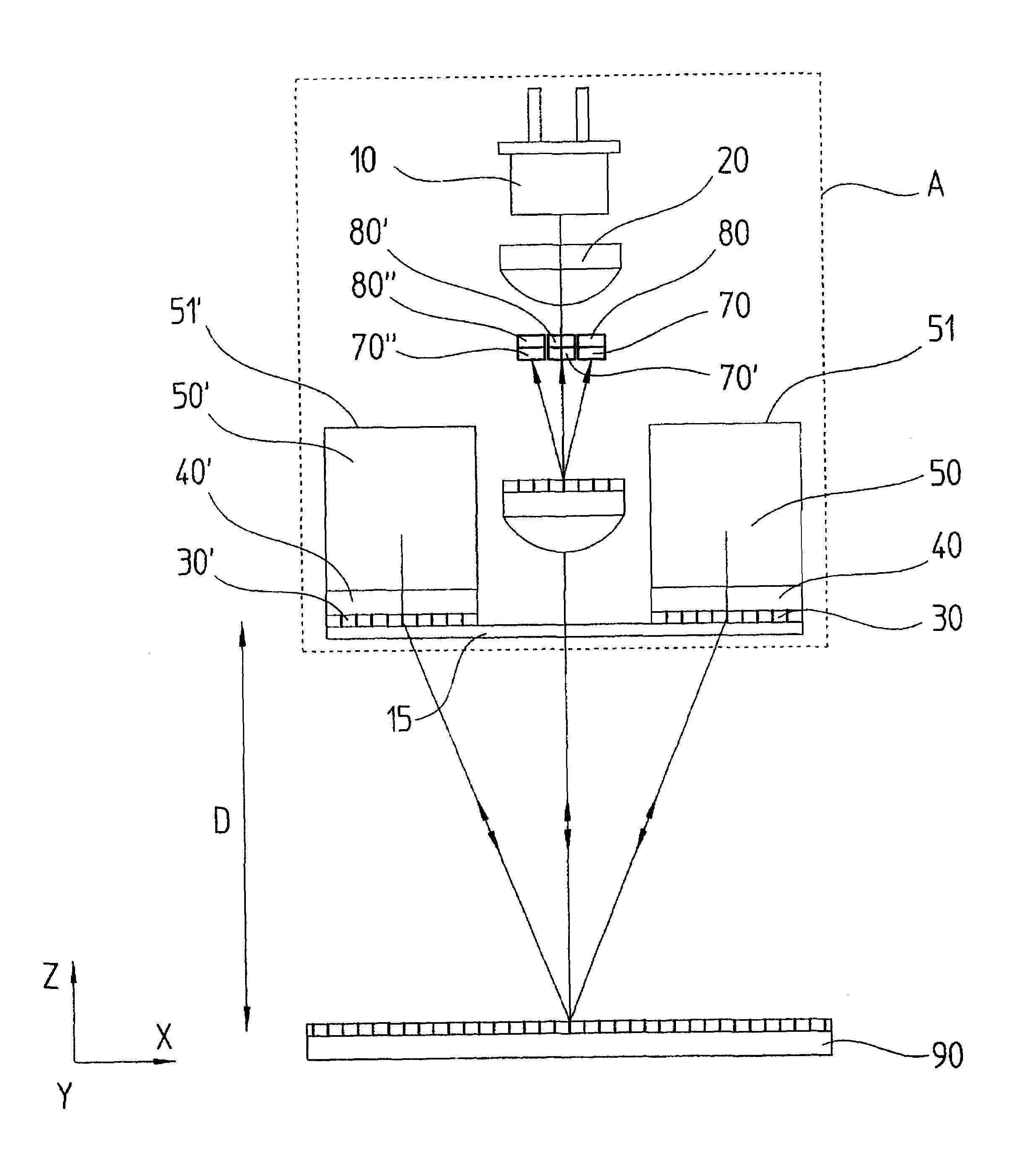
[0021]The beam path in a first embodiment of the position measuring device of the present invention is represented in an unfolded representation in FIG. 1. A four-grating transmitter, wherein all gratings, or graduations, have the same grating constant, or graduation period, is used in this example.

[0022]The scale grating 1 is vertically illuminated by a collimated laser beam emitted by a light source not represented in FIG. 1. The graduation extends along the x-direction. The light beams emanating by diffraction at the scale grating 1 are propagated to the first scanning grating 2, which is arranged at a distance D from the scale grating. In this case the + / − first orders of diffraction are important. The two light beams are straightened by being diffracted at the first scanning grating 2 and are propagated to the second scanning grating 3. In the course of this, each of the two light beams passes through two polarization-optical retardation elements 5, 5′, or 5″, 5′″, which are em...


PUM


Abstract

A position measuring device for detecting the relative position of a scanning unit and a scale. The position measuring device includes a scale and a scanning unit that is displaced with respect to the scale in a measuring direction. The scanning unit includes a scanning grating, a ridge prism and an optoelectronic detector element. The ridge prism having a ridge that is oriented parallel with the measuring direction, the ridge prism acts as a retro-reflector in a second direction which is aligned in a plane of the scale vertically with respect to the measuring direction.

Description

BACKGROUND OF THE INVENTION[0001]1. Field of the Invention[0002]The present invention relates to a position measuring device.[0003]2. Description of the Related Art[0004]In the course of chip production by wafer steppers it is necessary to position the mask and the substrate extremely accurately. For this purpose it is known to detect positional changes of the mask table by laser interferometers. In this connection the effects of disturbances in the air are detrimental, which in the end lead to positional noise and problems in regard to reproducibility. In order to keep the effects of heat expansion low, the measurement of the position of the substrate table or the mask table directly and relative to the optical imaging system would be advantageous. However, often the mounting of laser interferometers directly on the optical imaging system of the wafer stepper is not possible and not desired for reasons of space limitation and because of the thermal dissipation, so that it is necess...

Claims


Application Information

Patent Timeline
IPC IPC(8): G01B9/02G01B11/14G01D5/347G01D5/36G01D5/38G03F7/20G03F9/00
CPCG01D5/34715G03F7/70775G01D5/38
Inventor HOLZAPFEL, WOLFGANGSCHREIBER, ANDREAS
Owner DR JOHANNES HEIDENHAIN GMBH
Why Eureka
Try Eureka