Generation of M-ary digital signaling constellations directly at lightwave frequencies

a technology of digital signaling constellations and lightwave frequencies, applied in optics, instruments, electrical equipment, etc., can solve the problems of no similar device operating at optical frequencies, increased construction and maintenance costs, and increased technical complexity of modulators and demodulators used in generating transmitted signals and recovering data from received signals, so as to avoid potential rf-type problems, avoid system complexities, and reduce the effect of cos

Inactive Publication Date: 2006-03-28
LOCKHEED MARTIN CORP
View PDF23 Cites 24 Cited by
  • Summary
  • Abstract
  • Description
  • Claims
  • Application Information

AI Technical Summary

Benefits of technology

[0030]In a sixth aspect of the present invention, an optical link may have a receiver that includes a downconverter operative to downconvert the optical signals to signals in the radio frequency (RF) range, and a demodulator operative to demodulate the downconverted signals and recover the M-ary data word. Such a configuration may avoid a need for an optical phase locked loop.
[0031]As a result of implementing the present invention, RF electronics and associated system complexities, cost, power consumption, weight, and potential RF-type problems are all avoided. For example, by using a heterodyne downconverter at a relay satellite, the IF conventionally used in a bent pipe switching matrix is created from the optical signal and fed directly to the downlink just as though it came from an RF uplink or crosslink: the fact that it came to the satellite on an optical link is made transparent to the communications architecture of the satellite.
[0032]By using an intensity modulator and a phase modulator in sequence, any of the BEM constellations can be generated directly at the optical carrier. The resulting architecture is compatible with existing RF architecture, allowing for a smooth transition for conventional RF systems to a use of a direct photonic M-ary digital signaling constellation generator.

Problems solved by technology

The modulator and demodulator used in generating the transmitted signal and in recovering the data from the received signal have increased technical complexity.
These two penalties increase the expense of building and maintaining the communication link.
A problem with conventional coherent modulation techniques, however, is that they all require the use of a phase locked loop to implement the demodulation.
Unfortunately, there is no similar device that operates at optical frequencies to make the optical output frequency a function of an applied voltage.
However, these piezo devices have not demonstrated the tracking speed required to allow the optical phase locked loop to lock to the phase of an input signal.
Since an optical phase locked loop demodulator of this type is expensive and difficult to manufacture, coherent modulation is not practical for the commercial market, but has potential applicability for military applications where performance is often more important than cost.
This inability was due to limitations in the state of the art of thin film lithography.
The presence of simultaneous amplitude and phase modulation on intensity-modulated optical carriers, when transmitting using existing optical fibers over significant distances, may cause inter-symbol interference in the communication channel, which increases the bit error rates to values that are unacceptable for commercial quality-of-service (QOS) standards.
The simultaneous amplitude and phase modulation may also cause adjacent channel interference that also produces elevated values of bit error rates.
Unfortunately, these data handling / data routing components are excessively heavy in weight and consume too much power.
Another issue with ISL systems relates to transitions between RF and optical communications systems.
In conventional systems, there is no method for a heterodyne-up conversion from an IF frequency to a photonic frequency.

Method used


Image

  • Generation of M-ary digital signaling constellations directly at lightwave frequencies
  • Generation of M-ary digital signaling constellations directly at lightwave frequencies
  • Generation of M-ary digital signaling constellations directly at lightwave frequencies

Examples


Embodiment Construction

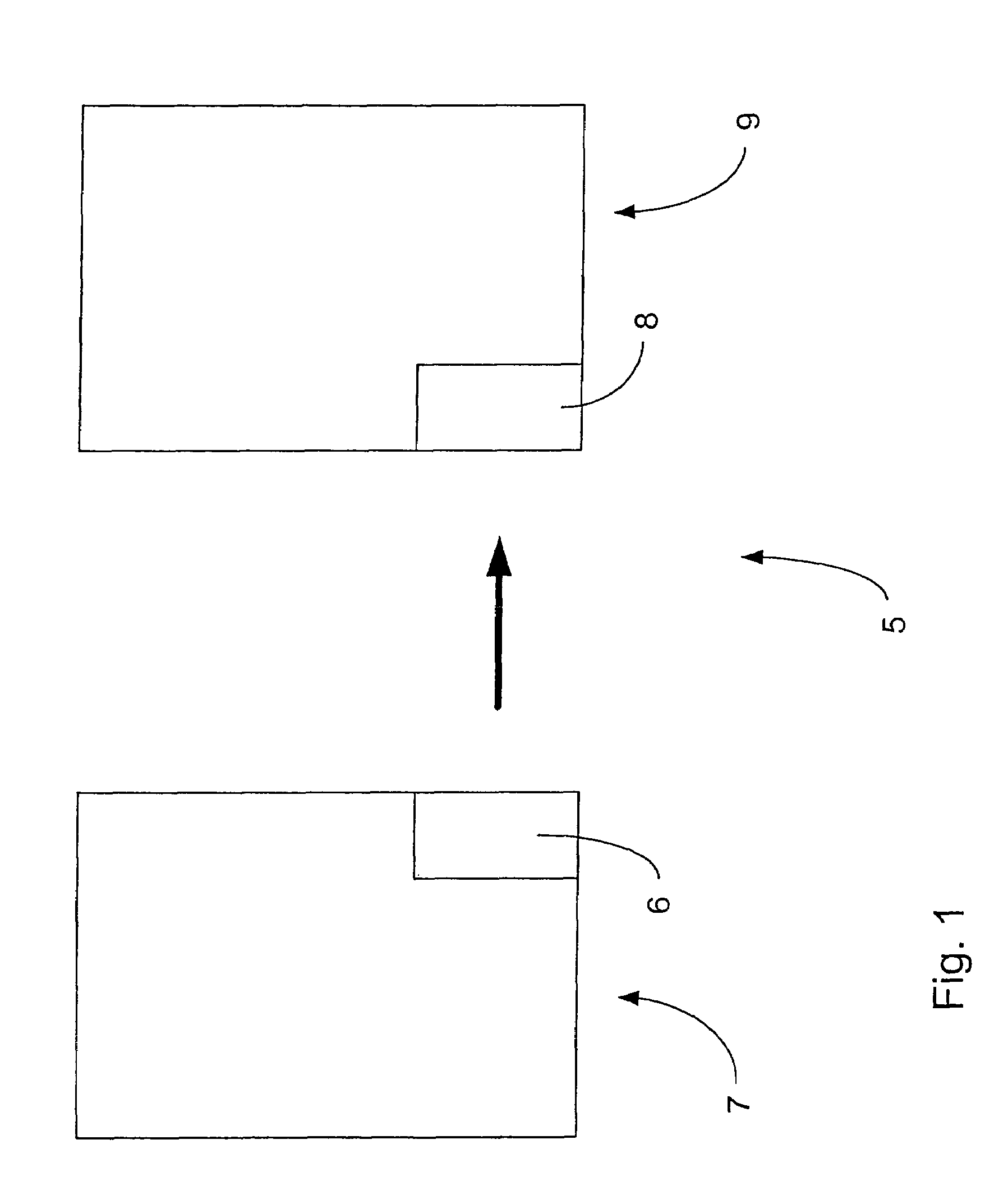
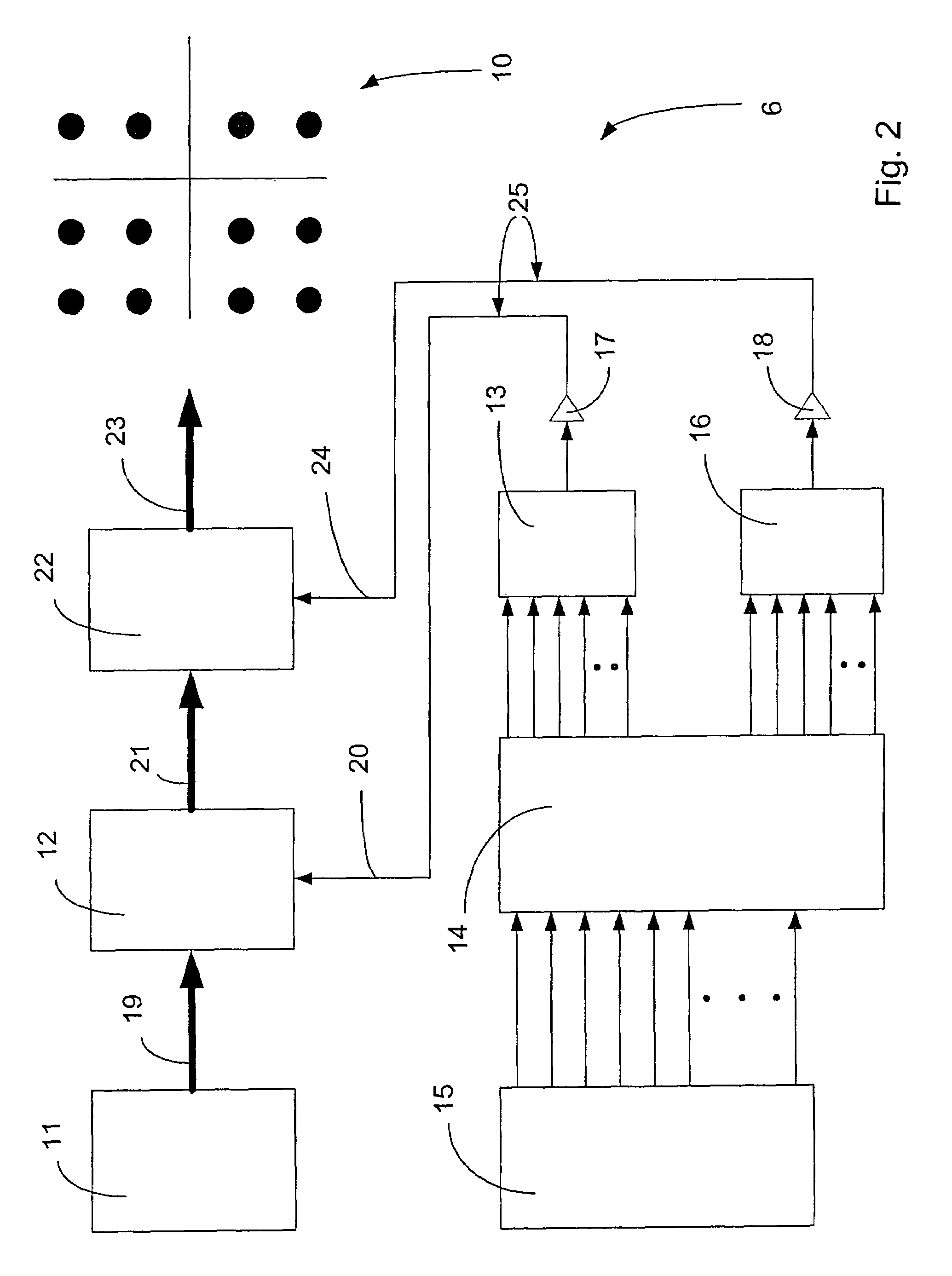
[0038]An optical communication system 5 of the present invention includes an optical transmitter 6 that may reside on a first satellite 7. as shown in FIG. 1. The transmitter 6 transmits an optical signal that propagates through space to an optical receiver 8 that may reside on a second satellite 9. Of course, a more practical system might include both a transmitter 6 and a receiver 8 on each of the satellites 7 and 9. but the system is shown in simplified form in FIG. 1 for ease of illustration. Although the system 5 is shown in exemplary fashion in an inter-satellite application, the present invention is equally applicable to other scenarios such as communication between space and ground and vice versa, as well as ground-to-ground scenarios. Among other things, the transmitter 6 includes a direct photonic M-ary digital signaling constellation generator and the receiver includes a frequency-locked heterodyne photonic downconverter.

[0039]The constellation generator is shown in furth...


PUM

PropertyMeasurementUnit
wavelengthaaaaaaaaaa
wavelengthsaaaaaaaaaa

Abstract

A coherent optical link includes a laser master oscillator operative to generate an amplitude- and phase-stable narrow linewidth optical carrier, a first programmable read-only memory (PROM) having an input for receiving and encoding an M-ary data word, a first digital-to-analog (D/A) converter operative to obtain the amplitude-encoded M-ary data word and output a corresponding analog signal, a Mach-Zehnder intensity modulator that obtains the analog signal and intensity-modulates the carrier based on the analog signal, an optical phase modulator having an input, and an optical waveguide that connects the Mach-Zehnder intensity modulator to the input of the optical phase modulator. The Mach-Zehnder intensity modulator and optical phase modulator may be formed into a single package. A modulation method includes modulating an intensity of an optical signal using a Mach-Zehnder intensity modulator, and then modulating the phase of the intensity-modulated optical signal.

Description

CROSS-REFERENCE TO RELATED APPLICATIONS[0001]This application claims priority from U.S. Provisional Patent Application No. 60 / 366,293, filed Mar. 21, 2002, entitled “GENERATION OF M-ARY DIGITAL SIGNALING CONSTELLATIONS DIRECTLY AT LIGHTWAVE FREQUENCIES”, the contents of which are incorporated herein by reference.FIELD OF THE INVENTION[0002]The present invention relates generally to modulation of optical signals and, more particularly, to techniques for coherent M-ary modulation.BACKGROUND OF THE INVENTION[0003]Optical communication typically involves an optical signal such as a beam of light in the ultraviolet, visible, or infrared wavelengths that has a characteristic that is varied or modulated. This modulated characteristic may be the intensity (amplitude), the phase, the frequency, the polarization, the location or duration of a pulse of light, and so forth. The pattern of modulation represents the information conveyed on the optical communication system. At one end of the optic...

Claims


Application Information

Patent Timeline
Patent Type & Authority Patents(United States)
IPC IPC(8): G02F1/15
CPCH04B10/50H04B10/5051H04B10/548H04B10/541H04B10/54
Inventor WILSON, KENNETH E.
Owner LOCKHEED MARTIN CORP
Why Eureka
Try Eureka