Method for information recording and apparatus therefor

a technology of information recording and apparatus, applied in the direction of digital signal error detection/correction, read-only discs, instruments, etc., can solve the problems of dust attached to the surface of the disk, information cannot be properly recorded on the disk, and light is liable to be scattered by small flaws on the face of the optical disk, so as to remove the influence of defects

Inactive Publication Date: 2006-03-28
PANASONIC CORP
View PDF8 Cites 4 Cited by
  • Summary
  • Abstract
  • Description
  • Claims
  • Application Information

AI Technical Summary

Benefits of technology

[0008]An object of the present invention is to provide an information recording method for stably recording digital video or digital audio information on an optical disk by removing the influence of defects as less as possible, and to provide an optical disk recording apparatus for carrying out the method.

Problems solved by technology

When the marks are made smaller, light is liable to be scattered by small flaws on the face of the optical disk or by particles of dust, fingerprints or the like attached to the surface of the disk.
As a result, information can not be recorded properly on the disk.
It is difficult to reduce flaws on the face of the disk and dust attached to the surface of the disk.
No information is recorded on a defective sector which is liable to cause errors owing to the defect.
Furthermore, a continuous long recording time is required, and the whole amount of the information is extremely large.
Defects are caused by flaws on the face of the disk in most cases.
Furthermore, the defect appears once at every turn of the disk periodically on about 1000 tracks.
This data processing causes very large data processing operation, and results in serious trouble in sequential recording of the video information supplied continuously.
In the worst case, recording operation is liable to be interrupted.

Method used


Image

  • Method for information recording and apparatus therefor
  • Method for information recording and apparatus therefor
  • Method for information recording and apparatus therefor

Examples


Embodiment Construction

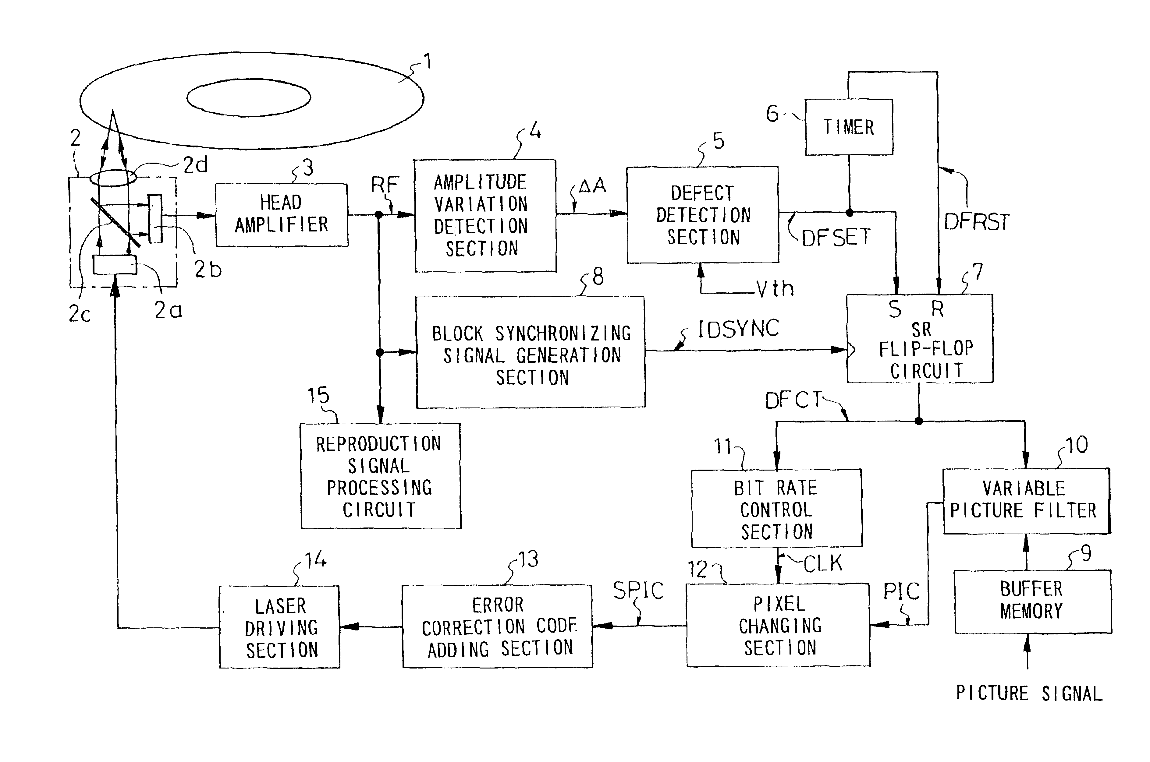
[0039]A method for recording information on an optical disk in accordance with a preferred embodiment of the present invention and an optical disk recording apparatus for carrying out the method will be described below referring to FIG. 1A to FIG. 8B.

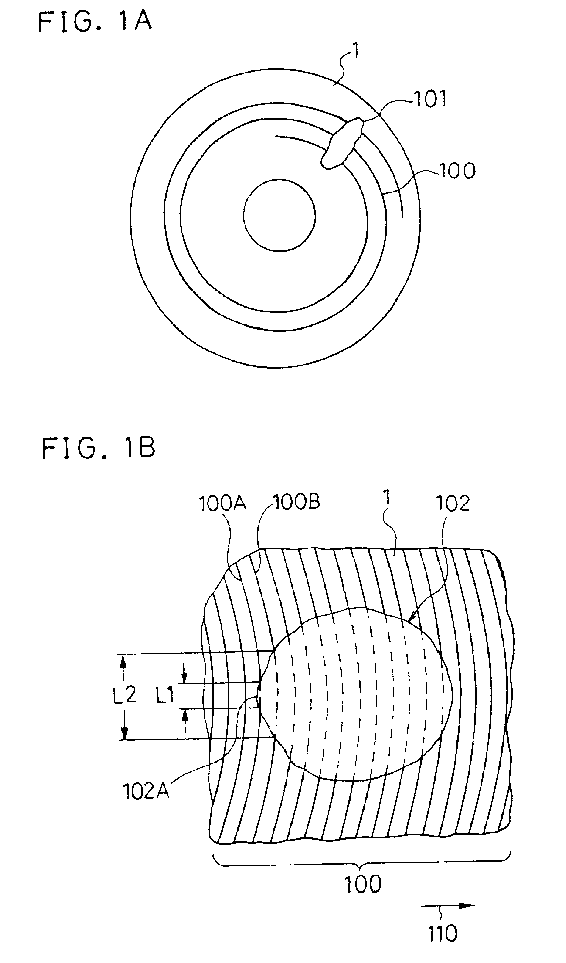
[0040]FIG. 1A is a plan view showing a conventional optical disk 1 used for the description of this embodiment. In the figure, a spiral track 100 is formed on the optical disk 1, and a defect 101 owing to flaws, particulates of dust, fingerprints or the like is present on the track 100. Concentric tracks may also be formed on the optical disk 1. The intervals between the tracks and the defect 101 are magnified for the sake of rendering the optical disk understandable. FIG. 1B is a magnified plan view showing a part of the optical disk 1, and shows a nearly circular defect 102 present on the plural tracks 100.

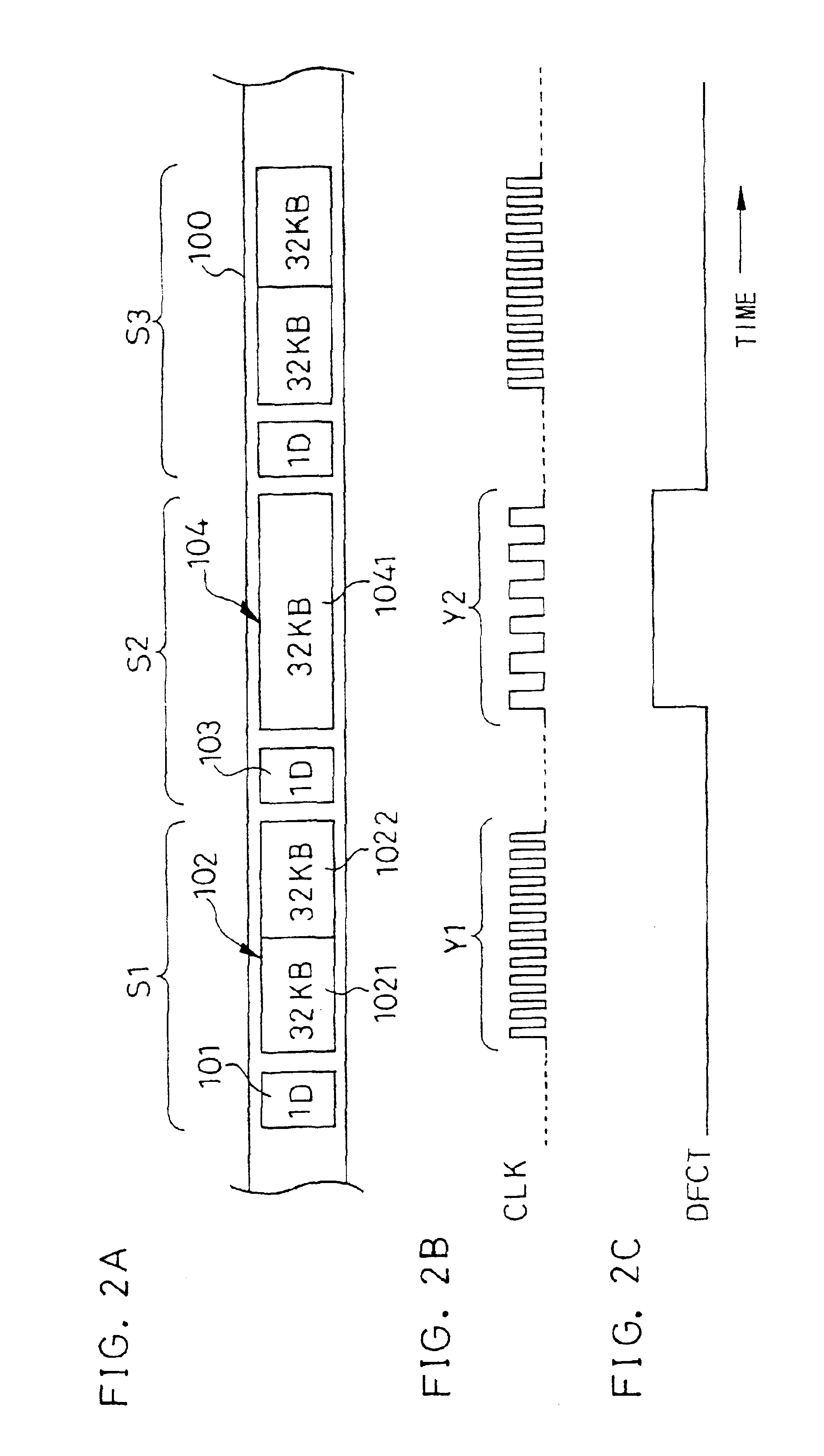
[0041]FIG. 2A is a plan view showing a part of the track 100 by using a linear belt. In FIG. 2A, the track 100 is divided into seg...


PUM

PropertyMeasurementUnit
diameteraaaaaaaaaa
recording densityaaaaaaaaaa
detection frequencyaaaaaaaaaa

Abstract

In areas on an optical disk wherein defects are detected frequently, recording is carried out while the recording density of information blocks is lowered and the amount of picture information is reduced at the same time so that digital video signals can be recorded even when defects owing to dust and flaws are present on the optical disk and so that picture losses can be prevented from occurring during reproduction.

Description

BACKGROUND OF THE INVENTION[0001]The present invention relates to an information recording method for recording digital video signals or digital audio signals on optical disks and to an information recording apparatus therefor.[0002]Optical disks are excellent in the reliability of information recording and in the preservation of recorded information, and are becoming popular as large-capacity exchangeable recording media. In recent years, because of a further increase of the recording capacity of the optical disk, the optical disk is developed to record video information, such as digital video information, and audio information, such as digital audio information, in addition to character information, such as document data and information processing programs. The capacity of an optical disk can be made larger by the increase of recording density. To increase the recording density, it is necessary to make marks (pits for example) smaller, which are means for recording information on ...

Claims


Application Information

Patent Timeline
Patent Type & Authority Patents(United States)
IPC IPC(8): H04N5/85H04N7/64G11B7/0037G11B7/0045G11B20/10G11B27/36H04N5/926H04N19/89
CPCG11B7/00375G11B7/0045G11B20/10009G11B27/36H04N5/85H04N5/926G11B2220/213G11B2220/2545G11B2220/2562G11B2020/00079
Inventor ISHIBASHI, HIROMICHI
Owner PANASONIC CORP
Why Eureka
Try Eureka