Image heating apparatus and image forming apparatus

a technology of heating apparatus and heating apparatus, which is applied in the direction of ohmic-resistance heating, shafts and bearings, instruments, etc., can solve the problems of reducing the temperature of the surface layer of the fixing roller, the inability to fix the unfixed toner on the recording material, and the inability to effectively prevent the production of glossiness and paper creases

Inactive Publication Date: 2006-03-28
CANON KK
View PDF11 Cites 16 Cited by
  • Summary
  • Abstract
  • Description
  • Claims
  • Application Information

AI Technical Summary

Benefits of technology

[0017]Accordingly, it is a principal object of the present invention to provide an image heating device and an image forming apparatus wherein a glossiness non-uniformity and paper crease production can be effectively prevented.
[0018]It is another object of the present invention to provide an image heating device and an image forming apparatus wherein a feeding performance of the belt is stabilized, and the image defect can be prevented.

Problems solved by technology

However, since a thickness of toner layer or layers on t recording material is larger in a full-color image than in a monochromatic image, and therefore, an amount of the deposited toner is large, it is desirable that length of the fixing nip measured in the feeding direction of the recording material (fixing nip width) is as large as possible, so that unfixed toner image an the recording material is heated at a temperature as low as possible for a long time in the printing step (fixing step).
On the other hand, if the thickness of the surface layer of heat resistive elastic member is increased, the surface layer temperature of the fixing roller lowers due to the decrease of the heat supply speed attributable to the heat conduction from the heating source to the surface layer of the fixing roller, even to such an extent that unfixed toner cannot be fixed on the recording material (fixing defect).
In order to avoid this, the printing speed is not enough to provide a required throughput (the number or prints per unit time), that is, not enough to follow the coming print data.
However, as an enlarging method for the nip width, there are only the increase of the roller diameter and the increase of the thickness of the heat resistive elastic member.
Therefore, there is a difficulty or limit in meeting the desire.

Method used


Image

  • Image heating apparatus and image forming apparatus
  • Image heating apparatus and image forming apparatus
  • Image heating apparatus and image forming apparatus

Examples


embodiment 1

(1) Example of Image Forming Apparatus

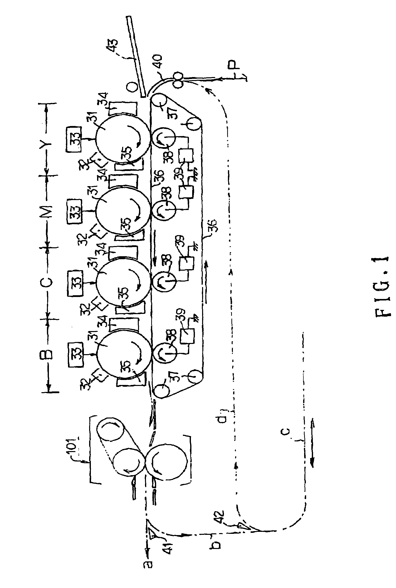
[0029]FIG. 1 is a schematic view of an example of an image forming apparatus provided with a fixing device as an image heating device according to an embodiment of the present invention. The image forming apparatus of this embodiment is a full color printer of a tandem type having an automatic both-side-printing function, using an electrophotographic process.

[0030]Designated by Y, M, C and B are first—fourth image forming stations disposed in this order from the right side in the drawing.

[0031]Each of the image forming stations Y, M, C, and B is an electrophotographic processing mechanism comprising an image bearing member in the form of a rotatable drum type electrophotographic photosensitive member 31, an exposure device 33 such as a charging device 32, a laser scanner, LED array or the like, a developing device 34, a cleaning device 35 and so on. The photosensitive member 31 is rotational driven in the clockwise direction indicated by an arro...

embodiment 2

[0082]The description will be made as to Embodiment 2.

[0083]In Embodiment 1, the configuration of the fixing roller 2 is such that outer diameter of the fixing roller 2 is non-linearly decreased from the central portion to the end portions. In the second embodiment, as shown in FIG. 6, (a) with exaggeration, the outer diameters of the opposite end portions are linearly decreased (positive taper configuration) so that fixing nip N has a flat surface configuration in which the widths at the end portions are large as shown in FIG. 6, (b). With this structure, too, the rotation diameter or the belt is larger in the central portion than at the end portions, the problem of shift of the belt toward the center can be avoided. The surface hardness of the fixing roller, the surface hardness of the pressing roller and the surface hardness of the fixing roller are the same as with Embodiment 1.

[0084]The combination of the fixing roller 2 having the positive taper configuration and the pressing ...

embodiment 3

[0092]Referring to FIG. 8, the description will be made as to Embodiment 3.

[0093]In Embodiments 2 and 3, the fixing belt 1 is extended around the fixing roller 2 and the heating roller 3 (two-shaft type). The present invention is applicable to a three-shaft structure using an auxiliary fixing roller 11, as shown in FIG. 8, with which the width of fixing the nip N is relatively larger, and the amount of heat applied to the recording material P and the toner image T is larger.

[0094]The description will be made as to.

[0095]As shown in FIG. 8, the auxiliary fixing roller 11 (second supporting member) is pressed against the pressing roller 4 with a predetermined pressure such that pressing roller 4 is wrapped by the fixing belt 1, by which the width of the fixing nip N is increased to increase the heating time for the recording material P and the toner image T, thus enhancing the fixing property.

[0096]The auxiliary fixing roller 11 may have a multi-layer structure comprising a metal roll...


PUM


Abstract

An image heating device includes a movable belt for heating an image on a recording material; a supporting member, having an elastic layer, for supporting the belt, the supporting member having an outer diameter which is larger in a central portion than at opposite end portions; a pressing rotatable member, pressed toward the supporting member with the belt interposed therebetween, for forming the nip for nipping and feeding the recording material; and pressing means for supporting opposite end portions of the supporting member and for pressing the supporting member and the pressing rotatable member toward each other; wherein a surface hardness of the supporting member through the belt is smaller than a surface hardness of the pressing rotatable member, and the pressing roller has a straight configuration in a longitudinal cross-section.

Description

FIELD OF THE INVENTION AND RELATED ART[0001]The present invention relates to an image heating apparatus and an image forming apparatus.[0002]An image forming apparatus of an electrophotographic type normally includes an image heating apparatus or fixing apparatus which receives a transfer material having toner electrostatically attracted thereon, the toner being made of resin material, magnetic material, coloring material or the like. In the fixing device, the transfer material is nipped and fed by a nip formed by heating means (roller, endless belt member or the like) and pressing means (roller, endless belt member or the like) which are press-contacted to each other, during which the toner is fused and fixed by heat and pressure. The present invention relates also to a heating apparatus of a heating belt type and an image forming apparatus provided with a heating apparatus comprising a flexible belt (film) which is movable and is heated by heating means, a back-up member supportin...

Claims


Application Information

Patent Timeline
Patent Type & Authority Patents(United States)
IPC IPC(8): G03G15/20G03G15/01F16C13/00H05B3/00
CPCG03G15/2064G03G15/206G03G2215/2016G03G2215/2064G03G2215/2032
Inventor ONO, KAZUAKIKACHI, MASAYOSHIMATSUURA, DAIGO
Owner CANON KK
Why Eureka
Try Eureka