Method and apparatus for compensating for distortion in radio apparatus

a radio apparatus and distortion compensation technology, applied in the direction of amplifier modification to reduce non-linear distortion, baseband system details, gain control, etc., can solve the problems of frequency asymmetric distortion and unsatisfactory suppression effect, and achieve the effect of satisfying the suppression effect of distortion

Inactive Publication Date: 2006-03-28
FUJITSU LTD
View PDF20 Cites 35 Cited by
  • Summary
  • Abstract
  • Description
  • Claims
  • Application Information

AI Technical Summary

Benefits of technology

[0014]Accordingly, an object of the present invention is to so arrange it that frequency asymmetric distortion can be compensated for so that a satisfactory distortion suppression effect can manifest itself.
[0015]A further object of the present invention is eliminate a variance in the distortion compensation effect caused by individual differences among devices.
[0016]In accordance with the present invention, distortion compensation coefficients for correcting distortion of a transmission power amplifier are stored in a memory, a distortion compensation coefficient conforming to a present transmit signal and a past transmit signal is read out of the memory, distortion compensation processing is applied to the transmit signal using this distortion compensation coefficient, the transmit signal to which distortion compensation processing has been applied is amplified and transmitted, and the distortion compensation coefficient is updated based upon the transmit signal before distortion compensation and an output signal from the transmission power amplifier. By thus obtaining a distortion compensation coefficient of the transmission power amplifier as a function of present and past transmit signals and applying compensation using this distortion compensation coefficient, frequency asymmetric distortion can be suppressed satisfactorily and a variance in the distortion compensation effect caused by individual differences among devices can be eliminated.

Problems solved by technology

Further, frequency asymmetric distortion differs depending upon individual differences among devices.
As a consequence, a frequency spectrum FS2 in a case where conventional distortion compensation processing (predistortion) has been carried out becomes as shown in FIG. 28, and a problem which arises is that although a distortion suppression effect is obtained, the suppression effect is not satisfactory.

Method used


Image

  • Method and apparatus for compensating for distortion in radio apparatus
  • Method and apparatus for compensating for distortion in radio apparatus
  • Method and apparatus for compensating for distortion in radio apparatus

Examples


first embodiment

[0054](B) First Embodiment

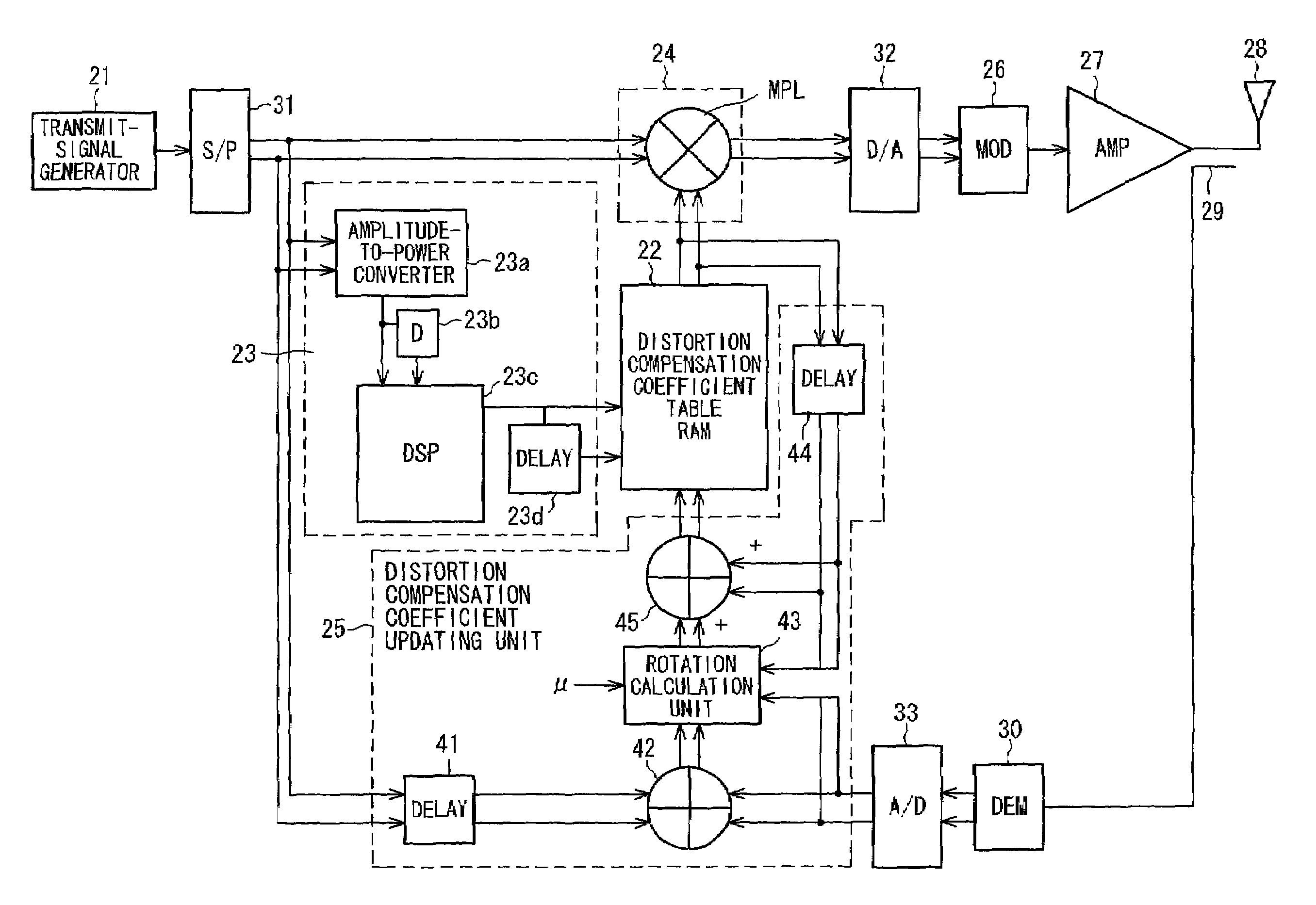
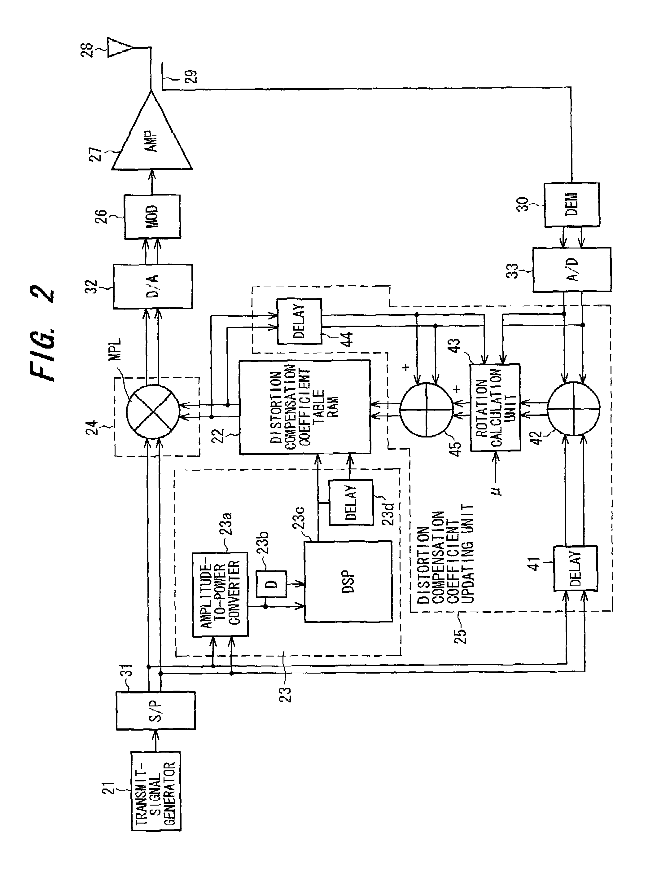
[0055]FIG. 2 is a diagram showing the structure of a first embodiment of the present invention. This is an example in which a distortion compensation scheme in a complex baseband system is adopted as the distortion compensation scheme. Components identical with those of the first embodiment are designated by like reference characters. The first embodiment is an example in which a distortion compensation coefficient is found as a function of power p(t) of the present transmit signal and a difference Δp between present transmission power and the transmission power that preceded it.

[0056]Numeral 31 denotes a serial / parallel (S / P) converter 2 for dividing serial data, which is output from the transmit-signal generator 21, alternately one bit at a time to convert the data to two sequences, namely an in-phase component signal (I signal) and a quadrature component signal (Q signal). Numeral 32 denotes a DA converter for converting, to analog signals, the distortio...

first modification

[0080](c) First Modification

[0081]In the first embodiment, it is assumed that a distortion compensation coefficient is a function of p(t), Δp, and the distortion compensation coefficient is stored in the distortion compensation coefficient table 22 at an address A [p(t),Δp] corresponding to p(t), Δp. However, an arrangement can be adopted in which it is assumed that a distortion compensation coefficient is a function of p(t), P(t−1), and the distortion compensation coefficient is stored in the distortion compensation coefficient table 22 at an address A [p(t),p(t−1)] corresponding to P(t), P(t−1). FIG. 11 is a diagram showing the structure of this first modification. This modification differs from the first embodiment of FIG. 2 in the following respects:

[0082](1) The DSP 23c is eliminated from the address generator 23, the latter generates the address A [p(t),p(t−1)] in which p(t) is the high-order address and p(t−1) the low-order address, and the delay circuit 23d generates the add...

second modification

[0086](c) Second Modification

[0087]In the first embodiment, it is assumed that a distortion compensation coefficient is a function of p(t), Δp, and the distortion compensation coefficient is stored at an address A [p(t),Δp] corresponding to p(t), Δp in the distortion compensation coefficient table 22. However, an arrangement can be adopted in which it is assumed that a distortion compensation coefficient is a function of power p(t) and a differential value p(t)′ of the envelope thereof, and the distortion compensation coefficient is stored in the distortion compensation coefficient table 22 at an address A [p(t),p(t)′] corresponding to P(t), P(t)′. FIG. 13 is a diagram showing the structure of this second modification. This modification differs from the first embodiment of FIG. 2 in the following respects:

[0088](1) The address generator 23 is provided with an arithmetic unit (implemented by a DSP) for calculating the differential value of the envelope, the latter generates the addre...


PUM


Abstract

Distortion compensation coefficients for correcting distortion of a transmission power amplifier are stored in a memory beforehand, a distortion compensation coefficient conforming to powers or amplitudes of a present transmit signal and a past transmit signal is read out of the memory, and distortion compensation processing is applied to the transmit signal using this distortion compensation coefficient. The transmit signal thus subjected to distortion compensation processing is then amplified by the transmission power amplifier and the amplified signal is transmitted, and the distortion compensation coefficient is updated based upon the transmit signal before distortion compensation and an output signal from the transmission power amplifier.

Description

[0001]This application is a continuation of International Application No. PCT / JP99 / 04037, filed Jul. 28, 1999.BACKGROUND OF THE INVENTION[0002]This invention relates to a method and apparatus for compensating for distortion in a radio apparatus and, more particularly, to a distortion compensation method and distortion compensation apparatus for suppressing non-linear distortion of a transmission power amplifier in a radio apparatus and reducing leakage of power between adjacent channels.[0003]Frequency resources have become tight in recent years and in wireless communications there is growing use of high-efficiency transmission using digital techniques. In instances where multilevel amplitude modulation is applied to wireless communications, a vital technique is one which can suppress non-linear distortion by linearizing the amplitude characteristic of the power amplifier on the transmitting side and reduce the leakage of power between adjacent channels. Also essential is a techniqu...

Claims


Application Information

Patent Timeline
Patent Type & Authority Patents(United States)
IPC IPC(8): H04B1/04H03F1/32H03G3/32H03G5/16
CPCH03F1/3247H03F1/3258H03G5/165H03F1/3294H03F2201/3224H03F2201/3233
Inventor NAGATANI, KAZUOOISHI, YASUYUKIKUBO, TOKUROODE, TAKAYOSHITAKANO, TAKESHIMANIWA, TORU
Owner FUJITSU LTD
Why Eureka
Try Eureka