
Direct injection internal combustion engine with NOx-reduced emissions

a technology of internal combustion engine and nox reduction, which is applied in the direction of machines/engines, electrical control, separation processes, etc., can solve the problems of low engine quietness, increased fuel consumption and hc/co emissions, and difficult to adapt and adjust to desired specifications. , to achieve the effect of low emission of pollutants and high engine load

Inactive Publication Date: 2006-04-04
VOLKSWAGEN AG
View PDF22 Cites 11 Cited by
  • Summary
  • Abstract
  • Description
  • Claims
  • Application Information

AI Technical Summary

Benefits of technology

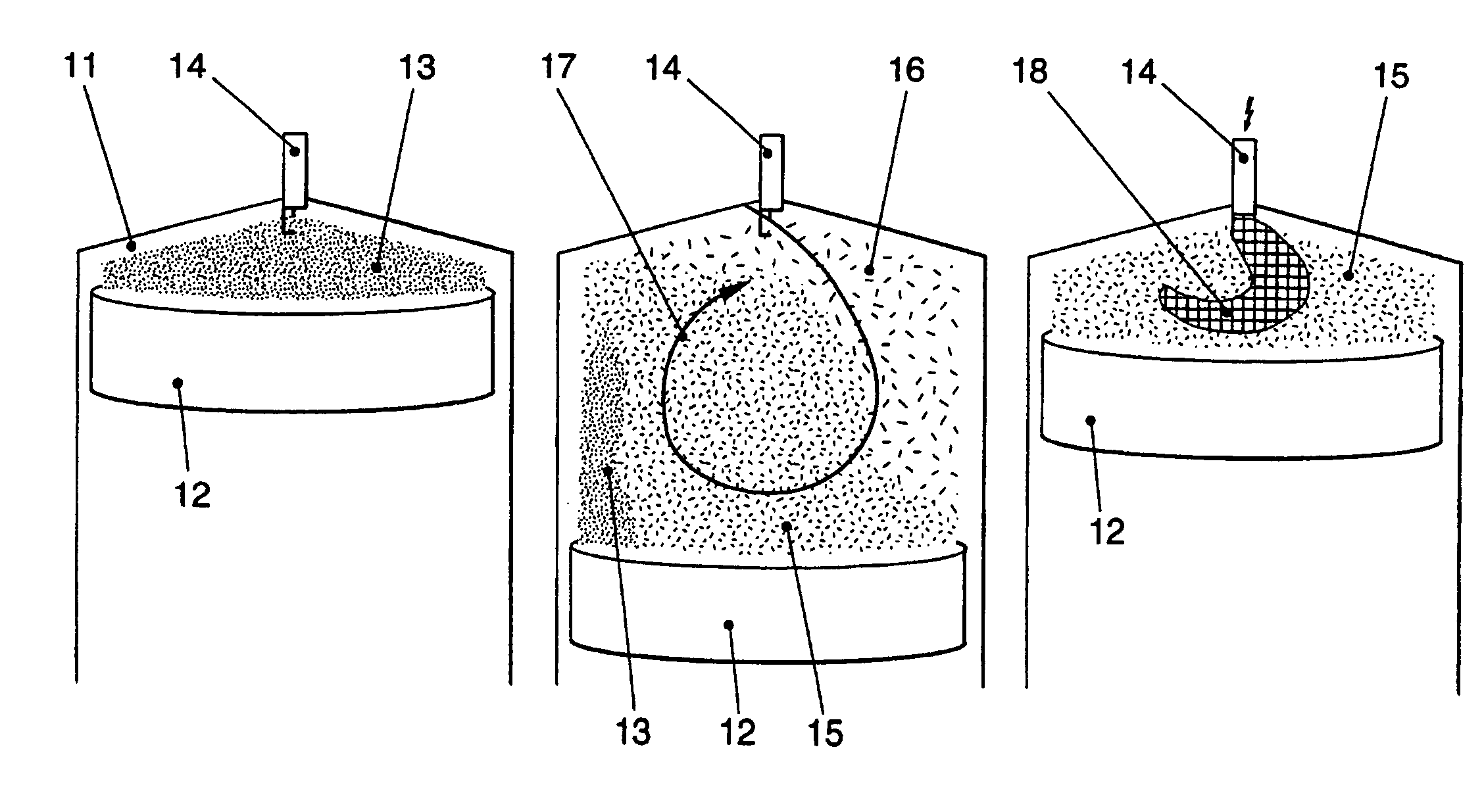
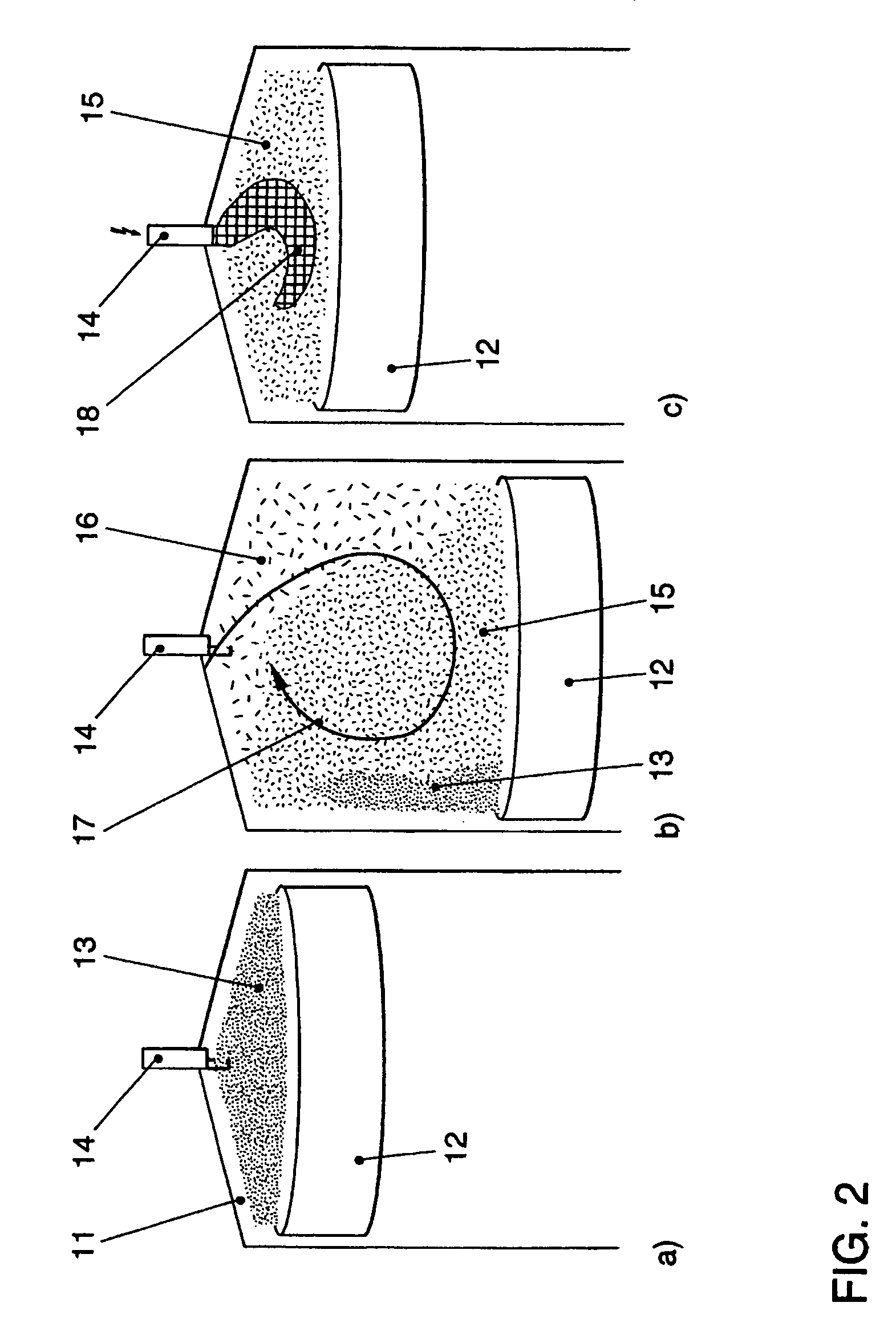
[0011]According to the invention, a special combination of individual exhaust gas-reducing steps allows an especially low emission of pollutants, particularly of NOx, to be obtained, so that now very low exhaust gas standards, such as for example D4, can be achieved even in direct injection internal combustion engines. This is made possible in a direct injection internal combustion engine by internal exhaust-gas recirculation (EGR), in particular in combination with external EGR, NOx-reducing exhaust-gas aftertreatment as well as a swirling movement of the incoming (fresh) gases, which runs substantially transverse to the axis of piston movement. Preferably, a tumble movement of the incoming gases is provided, which advantageously is produced by a tumble plate in the intake channel. In such a tumble movement, the incoming gases tumble rolling into the cylinder interior, the rolling movement proceeding about an axis transverse to the piston movement. The tumble plate advantageously is used with an as-needed switch from flow with tumble swirl to ordinary filling of the cylinder chamber, as is customary in for example lambda-1 operation (regeneration of storage catalyst, high engine load).
[0012]The combination of internal EGR with external EGR permits an increase in the exhaust-gas recirculation rate, so that the engine can operate with very low excess oxygen. Here, it is additionally possible to cool external EGR by means of an exhaust-gas recirculation cooler, so that the combustion chamber temperature does not get too high. External EGR is usually controlled by means of a valve.
[0015]With the present invention, a NOx sensor after the NOx-reducing step of exhaust-gas aftertreatment, may be used especially favorably, in particular in conjunction with a storage catalyst. In previous operating systems without the tumble movement, slight excess NOx emissions were possible, which were incorrectly evaluated by the NOx sensor as indicating that the storage catalyst needed to be regenerated, so that fuel consumption-increasing regeneration took place more than needed. NOx peaks are avoided by the use of the tumble gas movement, so that the NOx sensor after the storage catalyst signals permissible storage rates and hence storage-fill condition of the NOx storage catalyst only.
[0016]It has been found according to the invention that for optimal NOx reduction, as thorough as possible intermixing of the recirculated waste gas with fresh air should be obtained, since only in this way can the oxygen molecules participating in NOx formation be partially replaced by inert gas (exhaust gas) in the whole combustion chamber. According to the invention, production of rapidly burning local zones with a high percentage of oxygen, which contribute dis-proportionately to NOx formation, are avoided. This is of importance especially in the direct injection Otto engine, in order to be able to realize the advantages of internal exhaust-gas recirculation as much as possible.

Problems solved by technology

When exhaust-gas recirculation rates are too high, incomplete combustion takes place, owing to which fuel consumption and HC / CO emissions increase and the quietness of operation of the engine decreases.
In addition, the exhaust-gas recirculation rate in the dynamic operation present in an internal combustion engine, due to the time delay in the exhaust-gas recirculation line and the intake volume and the changing pressure conditions in the intake and exhaust-gas sides, is hard to adapt and adjust to desired specifications.

Method used


Image

  • Direct injection internal combustion engine with NOx-reduced emissions
  • Direct injection internal combustion engine with NOx-reduced emissions
  • Direct injection internal combustion engine with NOx-reduced emissions

Examples


Embodiment Construction

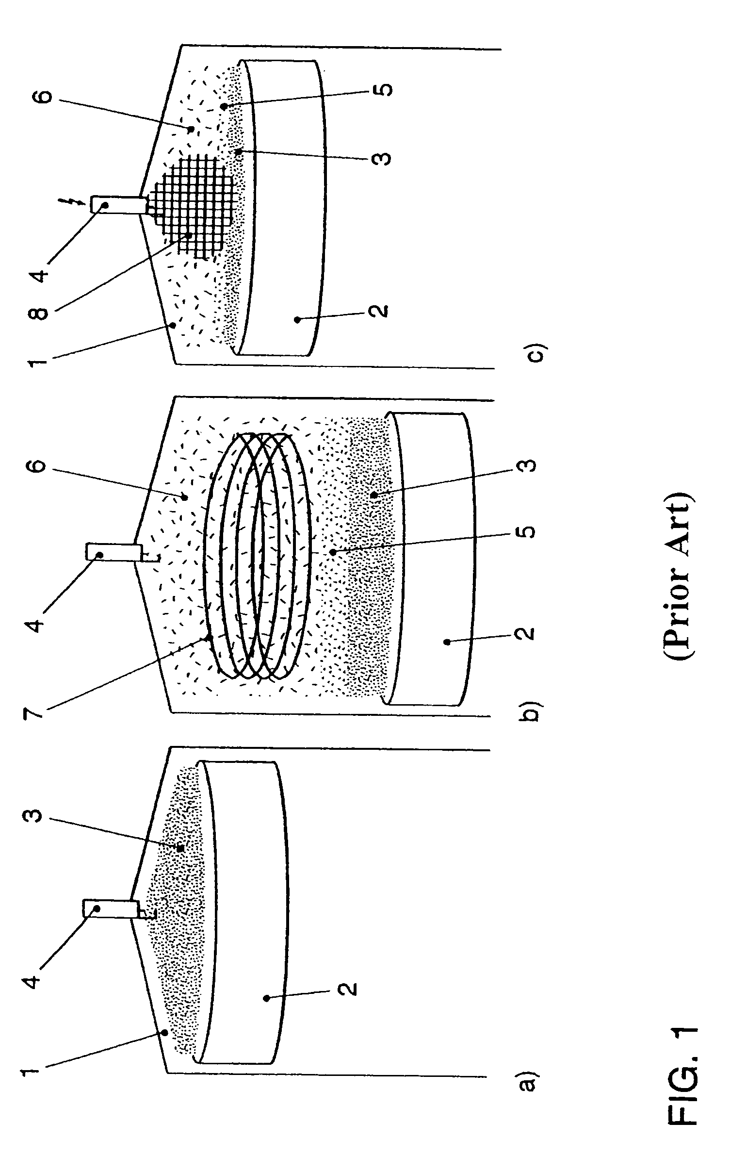
[0022]Studies according to the invention have shown that the mixture of fresh air 6 with exhaust gas 3 of internal exhaust-gas recirculation remaining in the combustion chamber 1 (FIG. 1a, piston 2 is at the top, exhaust gas 3 remains in the combustion chamber 1 owing to simultaneously open intake and exhaust valves (FIG. 4)) is suboptimal with swirl turbulence 7 wherein the swirl axis is aligned substantially to the axis of piston movement. The residual gas 3 of the internal EGR remains in the vicinity of the piston floor during the intake and compression strokes (FIG. 1b / c), due to the action of the swirl flow 7, the fresh gas 3 drawn in (containing predominantly fresh air) is then layered over the residual gas 3 in the intake stroke (FIG. 1b, piston 2 travels downward). Since the swirling gas movement 7 has only a few pulses in the direction of the piston movement, this layering (without substantial intermixing) is largely maintained during compression (FIG. 1c, piston travels up...


PUM


Abstract

A direct injection internal combustion engine, especially an Otto engine, is provided with layered lean operation and internal exhaust-gas recirculation. An exhaust-gas aftertreatment for reducing Nox using an Nox storage catalyst is also provided. This combination is to achieve the highest possible exhaust-gas recirculation rates with the lowest HC and Nox emission values. A tumble flow is provided for the incoming fresh gases, which may contain recirculated exhaust gas from external exhaust-gas recirculation. The swirl axis of the incoming fresh gases therefore extends substantially crosswise to the piston movement. This results in an emissions-reducing, optimal mixture inside the cylinder during the layered lean operation.

Description

BACKGROUND OF THE INVENTION[0001]The invention relates to a direct injection internal combustion engine.[0002]EP 0,560,991 B and EP 0,580,389 B disclose means for NOx reduction in internal combustion engines with lean operation. The principle applied is storage of the NOx produced, especially during lean operation of the engine, in a NOx storage catalyst and release of the stored NOx with simultaneous reduction by brief rich operation of the engine. This NOx conversion is also suitable especially in direct injection internal combustion engines. The NOx conversion allows relatively high conversion rates to be obtained where, especially for avoidance of raw NOx emissions, exhaust-gas recirculation may be used in combination with the NOx storage catalyst.[0003]Exhaust-gas recirculation reduces raw NOx emissions. This measure is especially important in direct injection Otto engines with a NOx-reducing exhaust-gas aftertreatment system in lean operation, in particular NOx storage catalys...

Claims


Application Information

Patent Timeline
IPC IPC(8): F02B31/00F01L13/00B01D53/94F01N3/08F01N3/20F01N3/24F01N3/28F02B17/00F02B23/08F02B23/10F02B75/12F02D13/02F02D21/08F02M26/01F02M26/23
CPCF02B31/00F02D21/08F02D41/0057F02D41/3023F02M25/0727F02M25/0752F02B17/005F01N2570/14Y02T10/47F02B2075/125F02D41/006F02D41/0065F02D2041/0015Y02T10/12Y02T10/146Y02T10/123F02M26/23F02M26/01Y02A50/20Y02T10/40F02B17/00
Inventor POTT, EKKEHARDKREBS, RUDOLFSTIEBELS, BERND
Owner VOLKSWAGEN AG
Learn More