Separated sanitary and storm sewer system

a sanitary and storm sewer technology, applied in the direction of sewer pipelines, water supply installation, transportation and packaging, etc., to achieve the effect of reducing the size of the pipe required, increasing the capa plant, and little or no treatmen

Inactive Publication Date: 2006-04-04
BERRY JR E WYNN
View PDF27 Cites 8 Cited by
  • Summary
  • Abstract
  • Description
  • Claims
  • Application Information

AI Technical Summary

Benefits of technology

[0009]A sewer system according to the present invention reduces the size of the pipe-required to carry sanitary effluent and / or increases the capa plant to treat sanitary effluent. Since the storm water and infiltrated water are separated from the sanitary effluent, they may require little or no treatment freeing plant capacity to treat the sanitary effluent. In some cases, treatment plant expansion can be delayed or eliminated.

Problems solved by technology

Since the storm water and infiltrated water are separated from the sanitary effluent, they may require little or no treatment freeing plant capacity to treat the sanitary effluent.

Method used


Image

  • Separated sanitary and storm sewer system
  • Separated sanitary and storm sewer system
  • Separated sanitary and storm sewer system

Examples


first embodiment

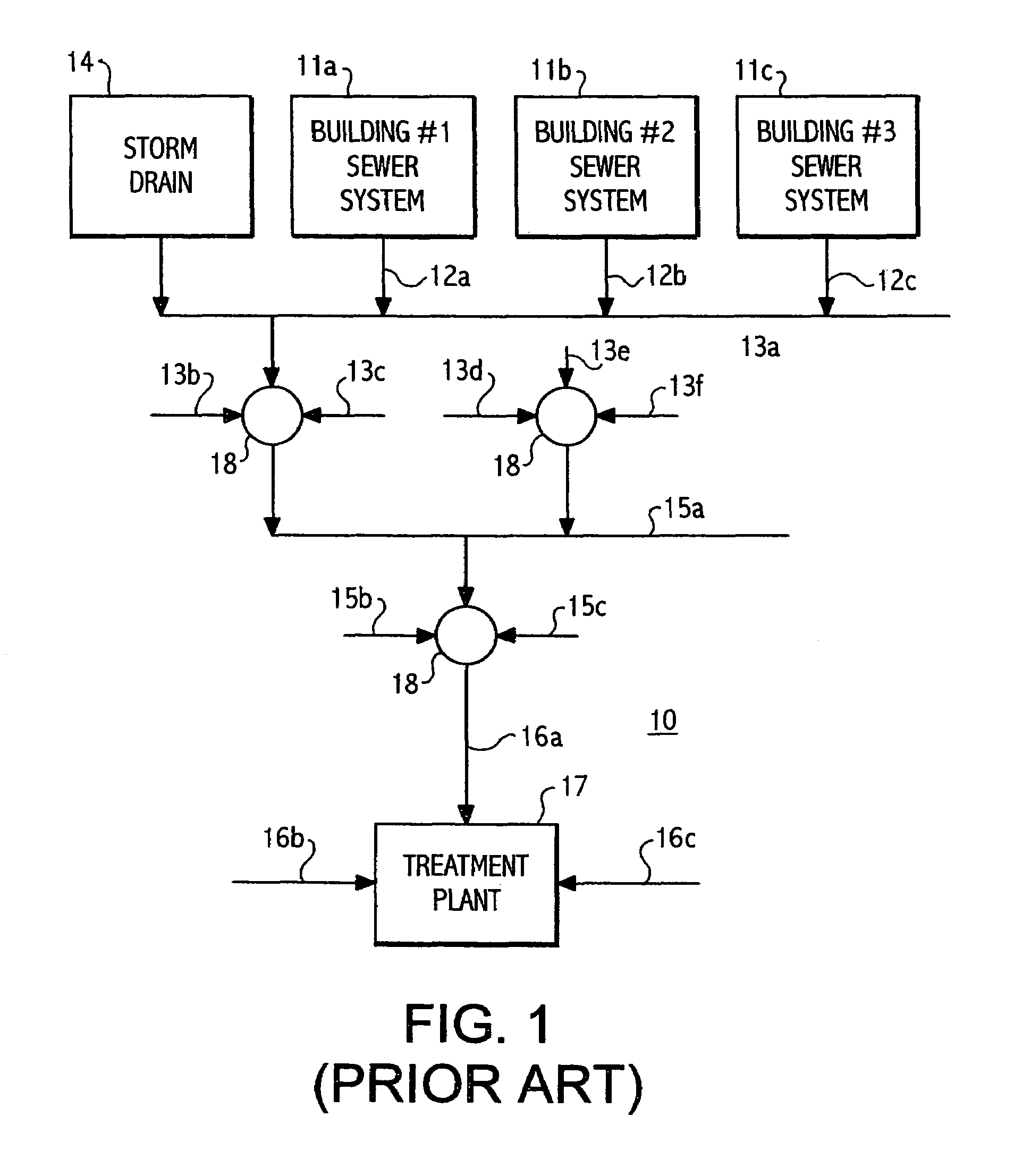
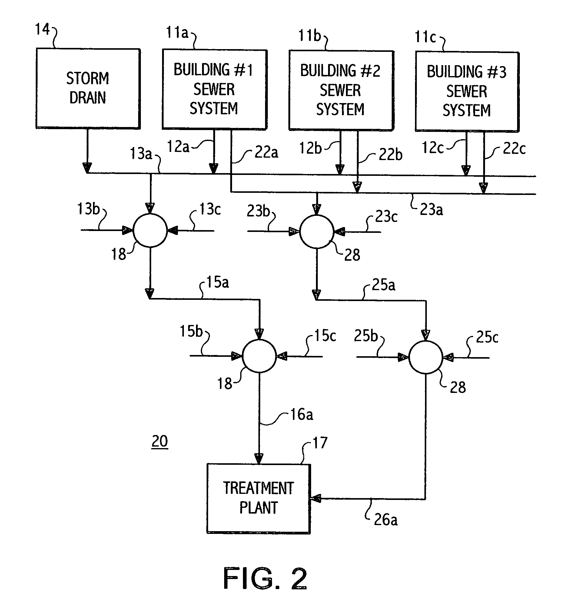
[0021]There is shown in FIG. 2 a first embodiment sanitary sewer system 20 according to the present invention wherein the sanitary effluent is completely separated from the remainder of the building wastewater. As also shown in FIG. 1, each of the building sewer systems 11a through 11c is connected by an associated one of the plurality of service lines 12a through 12c respectively to the collector line 13a. Thus, wastewater from such sources as sink drains, tub and shower drains, clothes washer drains and floor drains is combined to flow into the collector line 13a. However, the sanitary effluent from the toilets is connected to each of a plurality of sanitary effluent service lines 22a through 22c to carry the sanitary effluent to a sanitary effluent collector line 23a separate from the original collector line 13a. While new construction can be built with the required separated plumbing, existing building would require conversion. As an alternative, the new service lines 22a throug...

second embodiment

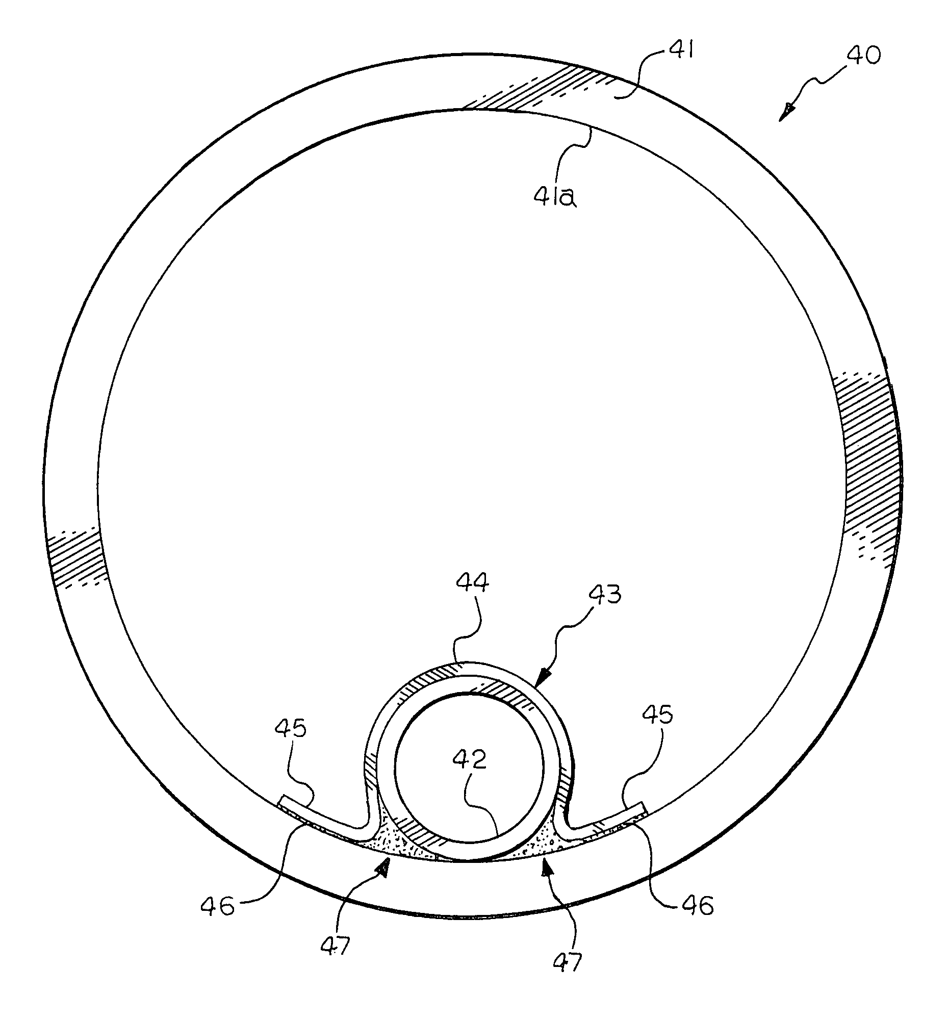
[0025]In some situations, it is desirable not to provide the sanitary effluent service lines 22a through 22c shown in FIG. 2, such as when retrofitting an existing system. There is shown in FIG. 5, a second embodiment sanitary sewer system 30 wherein the service lines 12a through 12c are connected to the sanitary effluent connector line 22a that runs parallel to the collector line 13a. Both of the collector lines 13a and 22a run into a manhole 31 wherein the line 22a can be inserted into the line 13a. From the manhole 31, the sanitary effluent lines run inside the corresponding existing sewer lines as in the system shown in FIG. 2.

[0026]The sewer system according to the present invention can be installed as a complete new system or during the repair of an existing system wherein the existing collector, trunk and interceptor lines are used as a first set of sewer lines that are connected to a source of storm water. The sanitary effluent lines according to the present invention are a ...


PUM


Abstract

An apparatus and method for improving the operation of sewer systems includes a first set of sewer lines connected to a source of other water and a second set of sewer lines of smaller diameter than the first sewer lines connected to sources of sanitary effluent, the first and second sets of lines being separately connected to a sewerage treatment plant. The second set of sewer lines can be attached to the interior surfaces of the first set of sewer lines by an adhesive material and fasteners. A liner can be provided in the first sewer lines with the second sewer lines being positioned between an exterior surface of the liner and the interior surface of second sewer lines.

Description

CROSS-REFERENCE TO RELATED APPLICATION[0001]This application is a continuation-in-part of the U.S. patent application Ser. No. 10 / 247,430, filed Sep. 19, 2002 now U.S. Pat. No. 6,698,442, which application claims the benefit of U.S. provisional patent application Ser. No. 60 / 401,714, filed Aug. 7, 2002.BACKGROUND OF THE INVENTION[0002]The present invention relates generally to an apparatus and a method for separating sanitary effluent from storm water and / or infiltrated water in a municipal sewer system.[0003]Municipal sewer systems include a web of pipes that convey wastewater from homes, businesses and industries and storm water from drains to treatment plants. The smallest pipes, typically twelve inches in diameter or less, are know as “collectors” that are connected to service lines running to the sanitary plumbing of buildings. The collectors are connected to “trunk lines”, typically larger than twelve inches in diameter, and carrying one to ten million gallons per day. The tru...

Claims


Application Information

Patent Timeline
Patent Type & Authority Patents(United States)
IPC IPC(8): F16L55/00E03F3/02
CPCE03F3/02Y10T137/0318Y10T137/402
Inventor BERRY, JR., E. WYNN
Owner BERRY JR E WYNN
Why Eureka
Try Eureka