Surgical instrument

a surgical instrument and a technology for guiding bones, applied in the field of surgical instruments, can solve the problems of long operation time, loose joints, and inability to provide stable joints, and achieve the effect of convenient operation and smooth operation

Inactive Publication Date: 2006-04-04
ASAHI KOGAKU KOGYO KK +1
View PDF28 Cites 22 Cited by
  • Summary
  • Abstract
  • Description
  • Claims
  • Application Information

AI Technical Summary

Benefits of technology

[0005]The present invention provides the advantages in that, in a surgical instrument, the bone plug can be easily kept at a right position of the surgical instrument during driving the bone plug into the bone tunnel and thus the surgeon can perform the operation smoothly.
[0009]In some embodiments of the invention, a proximal end portion of the guiding hole is inclined against the longitudinal axis of the elongated member and forms a side opening at an outer peripheral surface of the elongated member such that the guide wire can be inserted into the guiding hole from the side hole. Preferably, the proximal portion of the guiding hole is inclined against the longitudinal axis of the elongated. member at an acute angle such that the guide wire extending out from the side opening does not incline towards the distal end of the elongated member and thereby hinder the operation.
[0010]One or both of the guiding hole and the guiding wire may be applied with a coating for decreasing friction between the guiding hole and the guide wire so that the guide wire moves smoothly through the guiding hole.
[0011]The elongated member may include a grip portion having an outer peripheral surface with small bumps and dips which prevent the hand of the surgeon from slipping over the elongated member.

Problems solved by technology

Such methods for fixing ligaments, however, do not provide a stable joint between the ligament and the bone, but the joint tends to become loose.
Since the bone plug is driven into the bone inside a living body, e.g. inside the knee joint, the bone plug is hardly kept in a right attitude at a right position of the driving-instrument during the surgery, which in turn results in a rather long operation time.

Method used


Image

  • Surgical instrument
  • Surgical instrument
  • Surgical instrument

Examples


Embodiment Construction

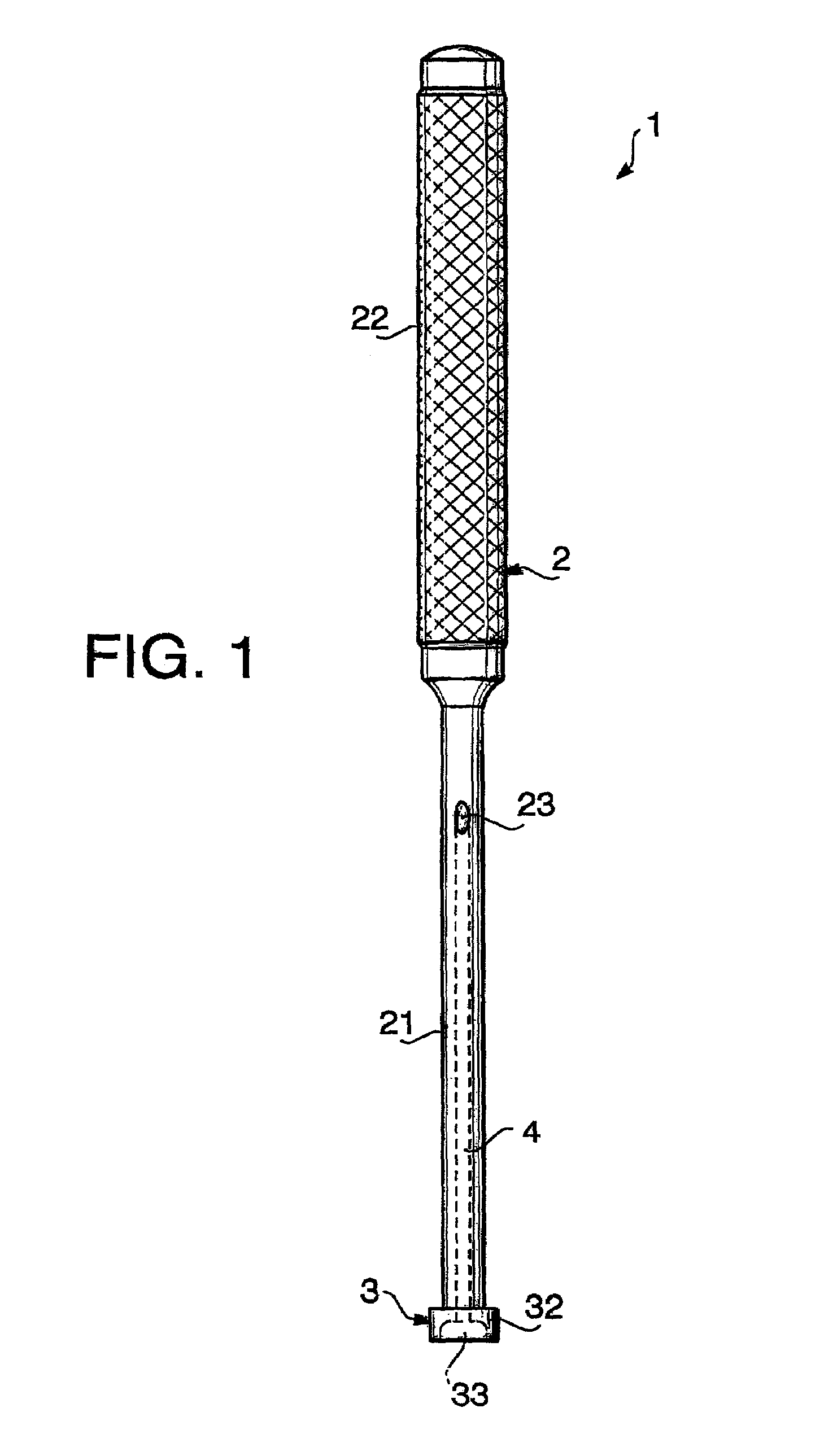
[0023]Hereinafter, a surgical instrument according to an embodiment of the invention will be described with reference to the accompanying drawings.

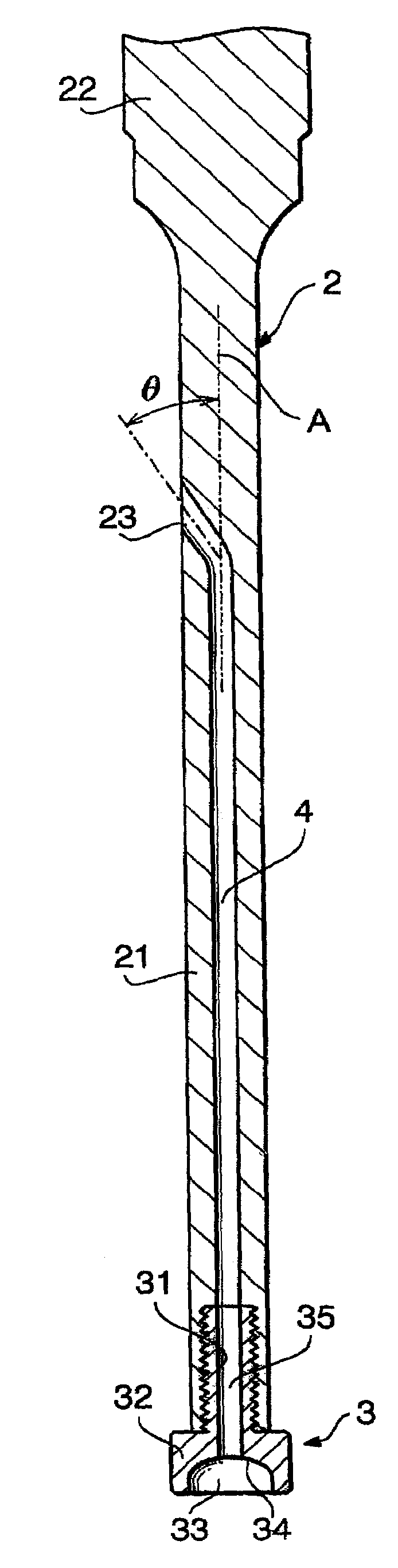
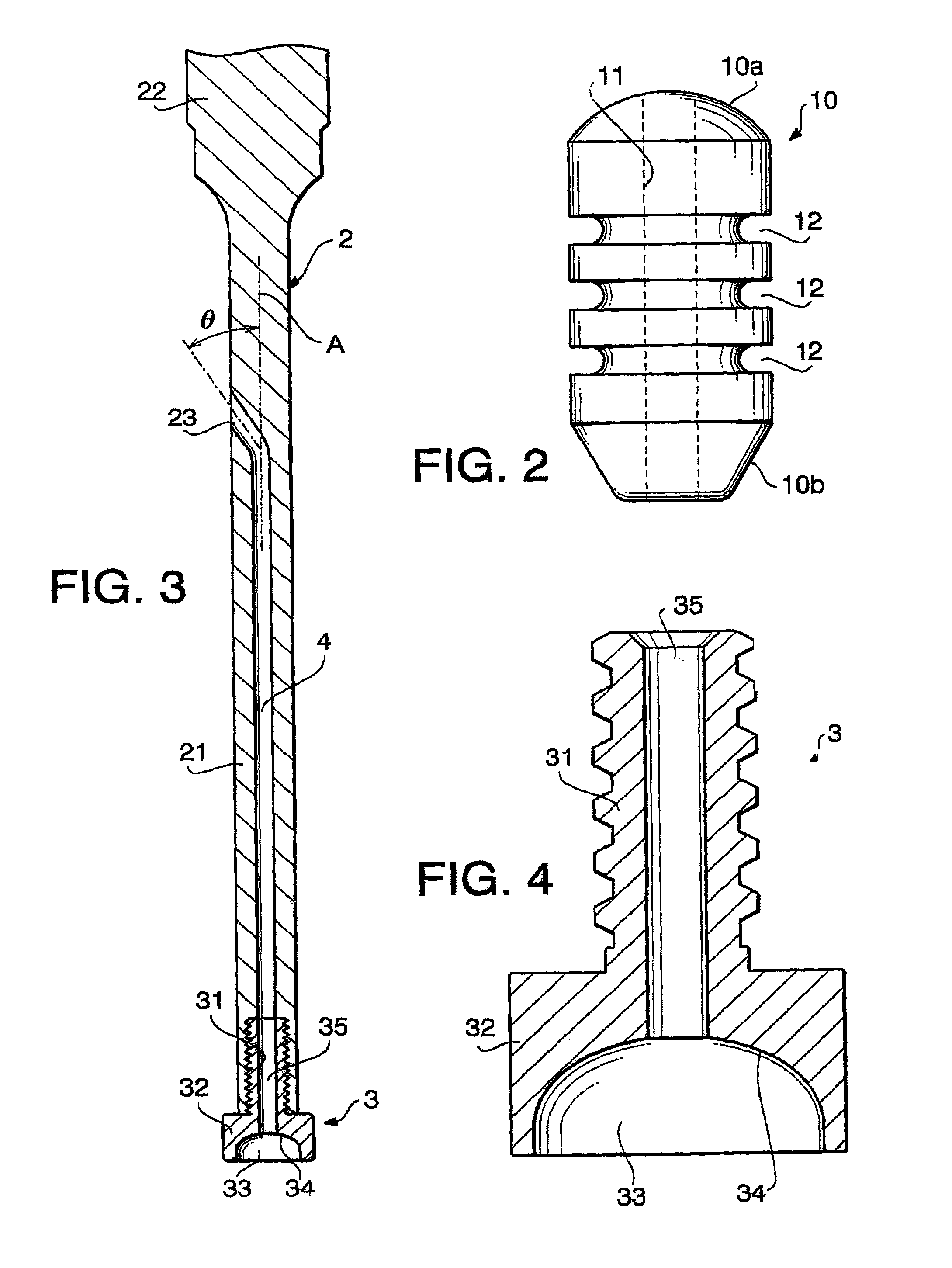
[0024]FIG. 1 is a side view of the surgical instrument 1, or a driving-instrument, according to the embodiment of the invention, and FIG. 2 is a side view of a bone plug 10 that is to be driven into a hole formed in a bone, or a bone tunnel, by the surgical instrument 1 shown in FIG. 1.

[0025]The bone plug 10 is to be driven into a bone tunnel together with an artificial ligament so that the ligament is fixed to the bone, as will be described later.

[0026]The bone plug 10 has a substantially cylindrical shape with a round proximal end 10a and a distal end 10b having a substantially conical shape with its top portion being cut away. A through hole 11 is formed along the center axis of the bone plug 10, and a plurality of circumferential grooves 12 are formed on the outer surface of the bone plug 10 spaced apart from each other, preferably at...


PUM


Abstract

There is provided a surgical instrument that includes an elongated body of which distal end is formed to press and drive a bone plug into a bone tunnel. The elongated body also has a guiding hole which is preferably formed along the longitudinal axis of the elongated body and in communication with a front opening formed at the distal end. The guiding hole is formed such that a guide wire can be inserted therein and extend out from the front opening. The guide wire is used to guide the bone plug towards the distal end of the surgical instrument and keep the bone plug there during driving it into the bone tunnel.

Description

BACKGROUND OF THE INVENTION[0001]The present invention relates to a surgical instrument, in particular, a surgical instrument for driving a bone plug into a hole formed in a bone for securing a ligament to the bone.[0002]Artificial materials such as artificial ligaments and reinforcement meshes, or organic materials such as patella bone-tendon, hamstring muscle, and fascia lata are used for anterior cruciate ligament reconstructions. In early stages of the reconstruction surgery, the reconstruction ligament was fixed to the bone using an anchor bolt, for example. Today, the artificial ligament is fixed to the bone by inserting it into a hole formed in the bone, or bone tunnel, and then closing the bone tunnel with a bone chip, an interference screw, or an inner button. Such methods for fixing ligaments, however, do not provide a stable joint between the ligament and the bone, but the joint tends to become loose.[0003]Recently, a new ligament fixing method is developed which provides...

Claims


Application Information

Patent Timeline
Patent Type & Authority Patents(United States)
IPC IPC(8): A61B17/58A61F2/00A61B17/56A61B17/17A61F2/08
CPCA61B17/1764A61F2/0805A61B17/1714
Inventor TAKEI, TSUNENORITANIGUCHI, YUKIOTOMINAGA, YOSHIE
Owner ASAHI KOGAKU KOGYO KK
Why Eureka
Try Eureka