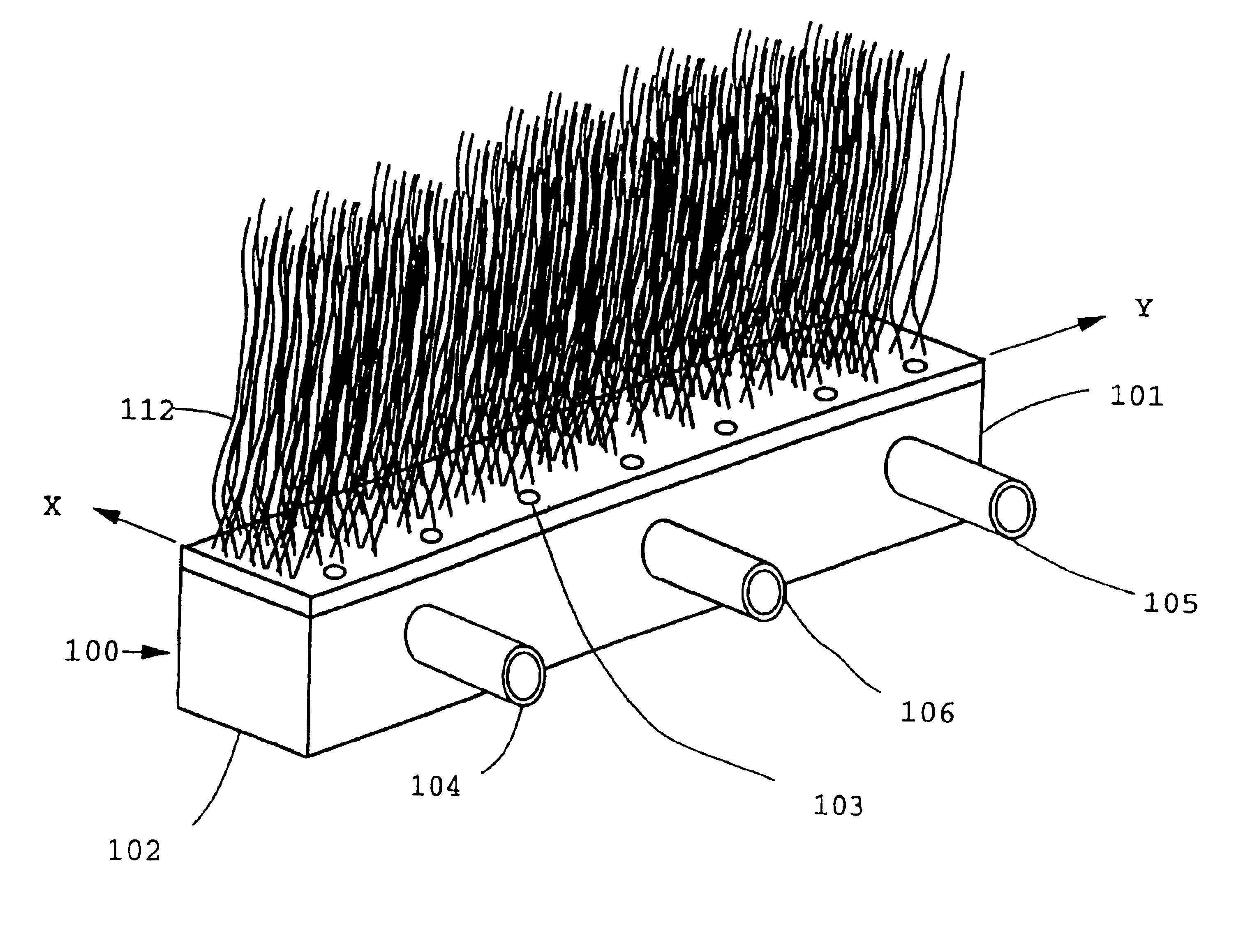
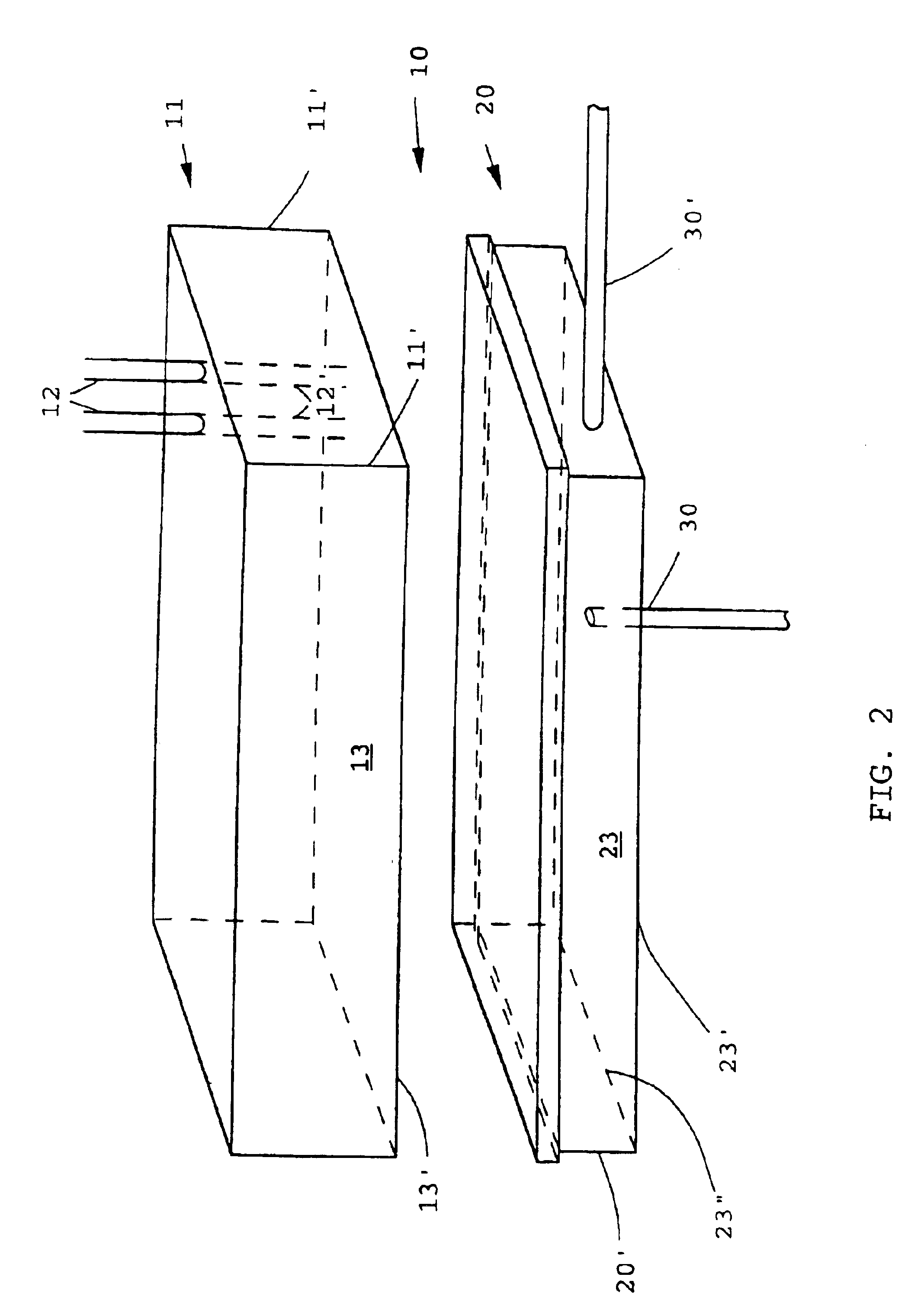
Apparatus incorporating potted hollow fiber membranes
a technology of hollow fiber membranes and apparatuses, applied in the field of membrane devices, can solve the problems that the bubbles of oxygen-containing gas to promote growth of microorganisms fail to build-up growth of microorganisms on the surface of fibers, and achieve the effect of high flux
- Summary
- Abstract
- Description
- Claims
- Application Information
AI Technical Summary
Benefits of technology
Problems solved by technology
Method used
Image

Examples
example
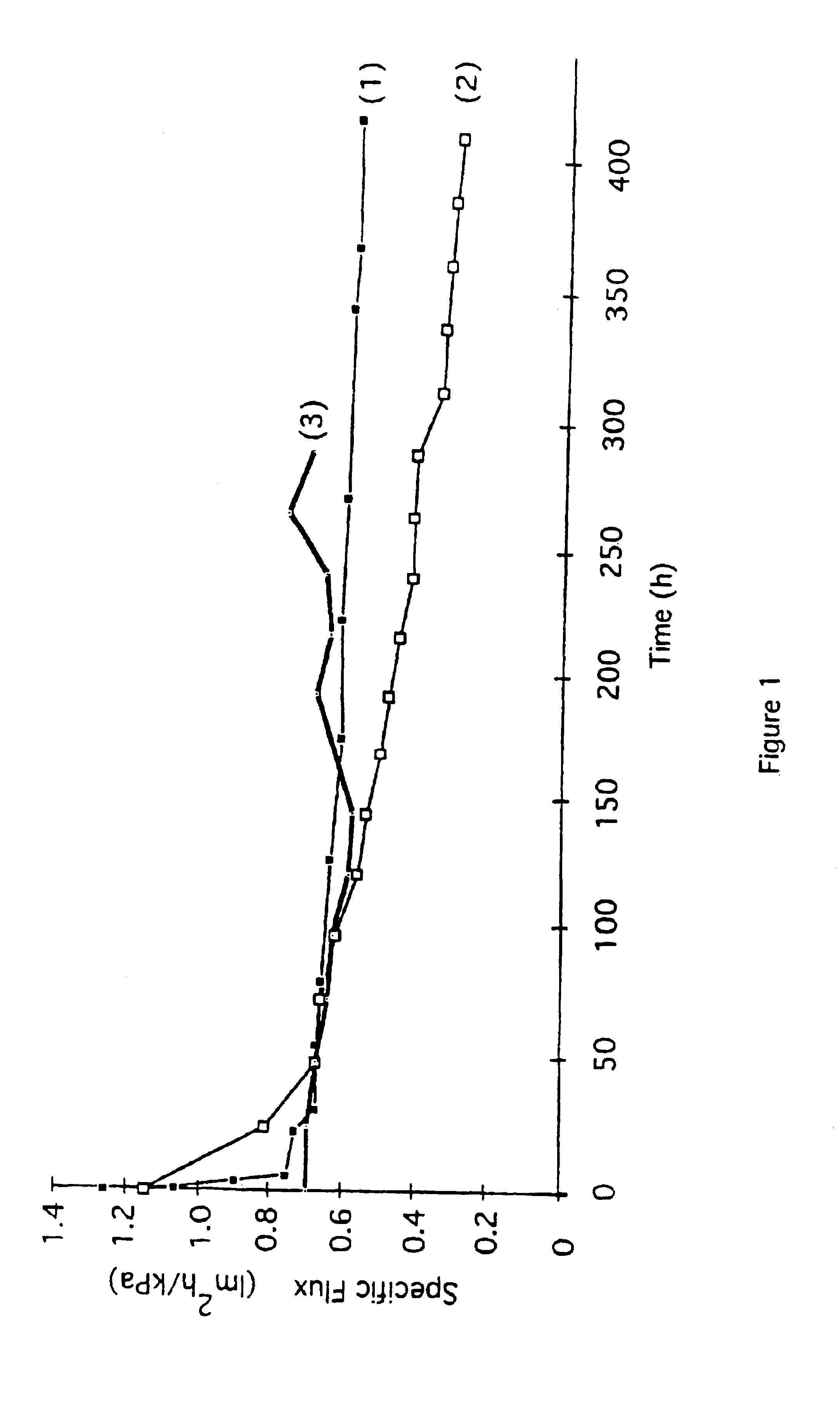
[0144]Microfiltration of an activated sludge at 30° C. having a concentration of 25 g / L (2.5% TSS) is carried out with a skein of polysulfone fibers in a pilot plant tank. The fibers are “air scrubbed” at a flow rate of 12 CFM (0.34 M3 / min) with a coarse bubble diffuser generating bubbles in the range from about 5 mm to 25 mm in nominal diameter. The air is sufficient not only for the oxidation requirements of the biomass but also for adequate scrubbing. The fibers have an outside diameter of 1.7 mm, a wall thickness of about 0.5 mm and a surface porosity in the range from about 20% to 40% with pores about 0.2 μm in diameter, both latter physical properties being determined by a molecular weight cut off at 200,000 Daltons. The skein which has 1440 fibers with a surface area of 12 m2 is wall-mounted in the tank, the vertical spaced apart distance of the headers being about 1% less than the length of a fiber in the skein. The opposed ends of the fibers are potted in upper and lower he...
PUM
| Property | Measurement | Unit |
|---|---|---|
| volume | aaaaa | aaaaa |
| volume | aaaaa | aaaaa |
| transmembrane pressure | aaaaa | aaaaa |
Abstract
Description
Claims
Application Information
 - R&D Engineer
- R&D Manager
- IP Professional
- Industry Leading Data Capabilities
- Powerful AI technology
- Patent DNA Extraction
Browse by: Latest US Patents, China's latest patents, Technical Efficacy Thesaurus, Application Domain, Technology Topic.
© 2024 PatSnap. All rights reserved.Legal|Privacy policy|Modern Slavery Act Transparency Statement|Sitemap