Method and apparatus for digital data synchronization

a digital data and synchronization technology, applied in the field of communication networks, can solve the problems of loosening some transparency of subscriber timing characteristics, and achieve the effects of narrowing the bandwidth of the desynchronizer pll, loosening some transparency of subscriber timing characteristics, and reducing wait time jitter

Inactive Publication Date: 2006-04-04
CIENA
View PDF8 Cites 27 Cited by
  • Summary
  • Abstract
  • Description
  • Claims
  • Application Information

AI Technical Summary

Benefits of technology

[0012]At the terminating node, the pointer processor demaps each SPE tributary, and extracts the timing estimate F. The timing estimate F extracted from the SPE tributary is used in place of the elastic store fill signal to steer the desynchronizer Phase locked Loop (PLL). Consequently, the PLL output constitutes a recovered data clock signal having a frequency f4 which more closely approximates the original frequency f1 of the subscriber traffic. As a result, by reading subscriber data from the tributary FIFO at a timing of the recovered data clock, the desynchronizer framer can generate a recovered subscriber signal in which the original timing is substantially restored.
[0013]An important attribute of the present invention is that the timing estimate F enables the transparent transport of the subscriber's original phase variations over a reasonable bandwidth (e.g. 100 Hz–1 KHz). Traditionally, waiting time jitter is reduced by narrowing the bandwidth of the desynchronizer PLL. However, very narrow filtering at the desynchronizer PLL has the effect of attenuating the subscriber signal's phase variations and hence looses some transparency of the subscriber timing characteristics. The present invention overcomes this limitation by the accurate measurement of subscriber phase / frequency at the synchronizer. This information is encoded within the STS frame (in the form of timing estimate F) and used to steer the desynchonizer PLL, which substantially eliminates waiting time jitter.
[0014]Another important attribute of the present invention is that, unlike conventional systems, an elastic store fill signals and are not used to control insertion of stuff bytes at either the transmitting or receiving nodes. This avoids problems due to the fill signals containing clock noise, cross-talk from other signals, and data patterning. Instead of the elastic store fill signals, the present invention uses the timing estimate F as an accurate measurement of the subscriber phase / frequency to drive stuffing at the transmitting node and generation of the recovered data clock signal at the receiving node.

Problems solved by technology

However, very narrow filtering at the desynchronizer PLL has the effect of attenuating the subscriber signal's phase variations and hence looses some transparency of the subscriber timing characteristics.

Method used


Image

  • Method and apparatus for digital data synchronization
  • Method and apparatus for digital data synchronization
  • Method and apparatus for digital data synchronization

Examples


Embodiment Construction

[0028]FIG. 2A schematically illustrates a synchronizer and method of synchronization at an originating node whereas FIG. 2B illustrates the corresponding desynchronizer and method of desynchronization at a receiving node in a SONET or SDH network.

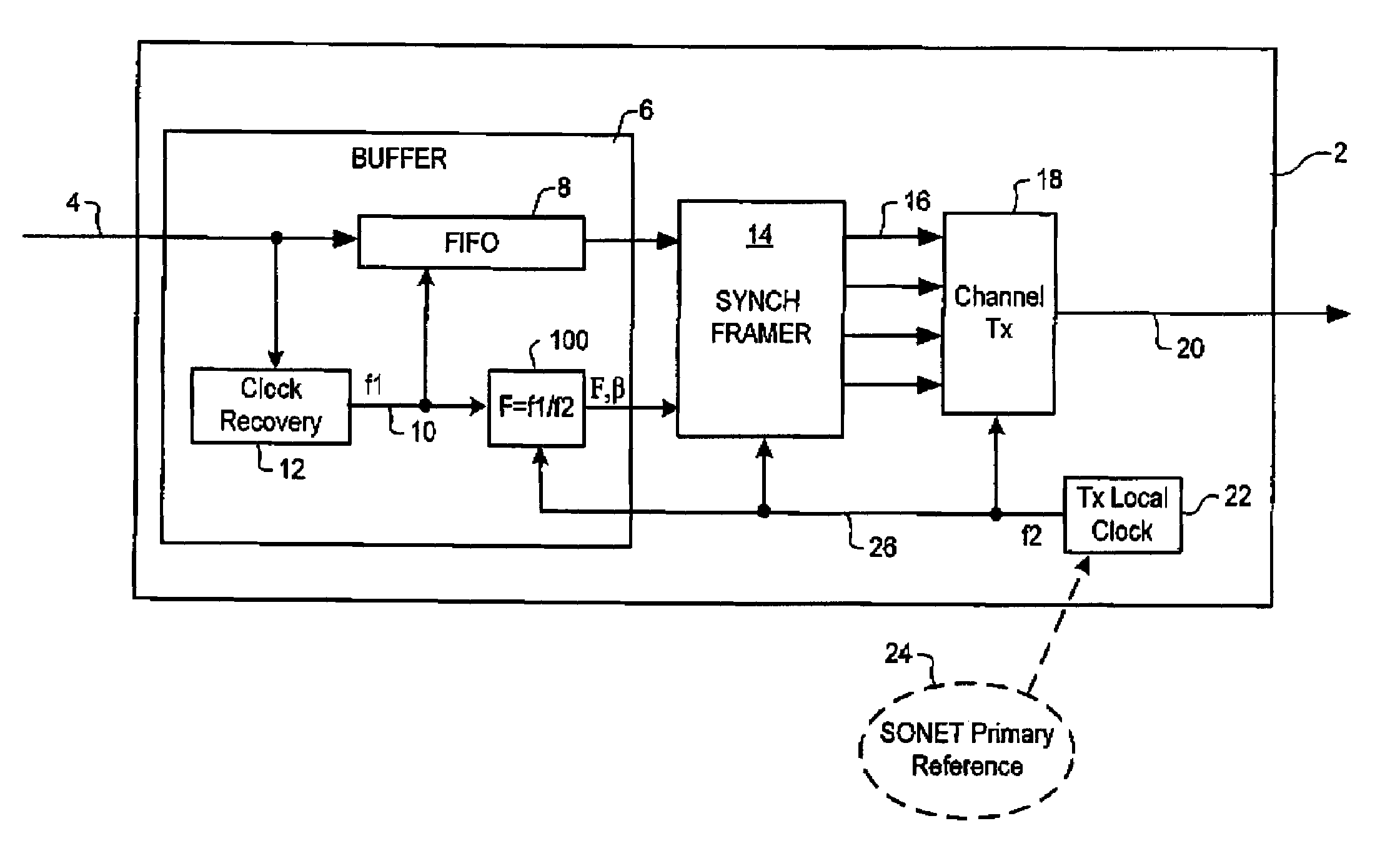
[0029]In general, the present invention teaches methods of rate adapting an asynchronous subscriber signal on to SONET STS frames without incurring waiting time jitter, by measuring the phase and frequency of the (asynchronous) subscriber signal and encoding this information into the frame overhead. Thus, as shown in FIG. 2A, a multi-bit digital timing estimate (F) is calculated (at 100) to indicate the difference between the tributary data rate f1, and the Tx local clock frequency f2. In the embodiment of FIG. 2A, the timing estimate F is computed as a ratio between f1 and f2. In other embodiments, the timing estimate F may be computed as a phase difference between the subscriber data signal and Tx local clock signal, calculated at the tim...


PUM


Abstract

Synchronization and desynchronization of a data signal transported in a synchronous frame across a synchronous communications network, such as SONET / SDH, reduces waiting-time jitter. A timing estimate (F) indicative of a relationship between a data rate (f1) of the data signal and a reference frequency (f2) of the synchronous communications network is calculated and communicated through the synchronous communications network, for example in the Synchronous Payload Envelope of a SONET frame. The data signal is recovered using a desynchronizer Phase-Locked Loop steered by the timing estimate (F). The timing estimate (F) can be any one or more of: a ratio between the data rate (f1) and the reference frequency (f2); a difference between the data rate (f1) and the reference frequency (f2); and a phase difference between a recovered data clock signal associated with the data rate (f1) and a reference clock signal associated with the reference frequency (f2).

Description

FIELD OF THE INVENTION[0001]The present invention relates to communications networks, and in particular to methods of synchronization or desynchronization of a data signal transported across a SONET or SDH network.BACKGROUND OF THE INVENTION[0002]Within the modern network space, the Synochronous Optical Network (SONET) / Synchronous Digital Hierarchy (SDH) protocol is becoming increasingly popular as a mechanism for data transport. In this respect, SDH is the European equivalent of the SONET transmission standard. Accordingly, all references in this application to SONET should be understood to also refer to SDH.[0003]A significant amount of SONET / SDH infrastructure has been installed, particularly within the network core. This SONET infrastructure is used to transport asynchronous subscriber signal traffic having differing formats, such as Asynchronous Transfer Mode (ATM), Internet Protocol (IP), etc. In order to facilitate this functionality, various known methods are provided for ma...

Claims


Application Information

Patent Timeline
Patent Type & Authority Patents(United States)
IPC IPC(8): H04L7/00H04J3/00H04J3/06H04J3/07H04Q11/04
CPCH04J3/0647H04J3/076H04J2203/0089
Inventor ROBERTS, KIM B.GAGNON, RONALD J.SHIELDS, JAMES A.
Owner CIENA
Why Eureka
Try Eureka