
Collimator, X-ray irradiator, and X-ray apparatus

a technology of x-ray irradiator and collimator, which is applied in the field of collimator, x-ray irradiator, and collimator, and achieves the effect of reducing the size and sacrificing the apertur

Inactive Publication Date: 2006-04-04
GE MEDICAL SYSTEMS INC +1
View PDF13 Cites 15 Cited by
  • Summary
  • Abstract
  • Description
  • Claims
  • Application Information

AI Technical Summary

Benefits of technology

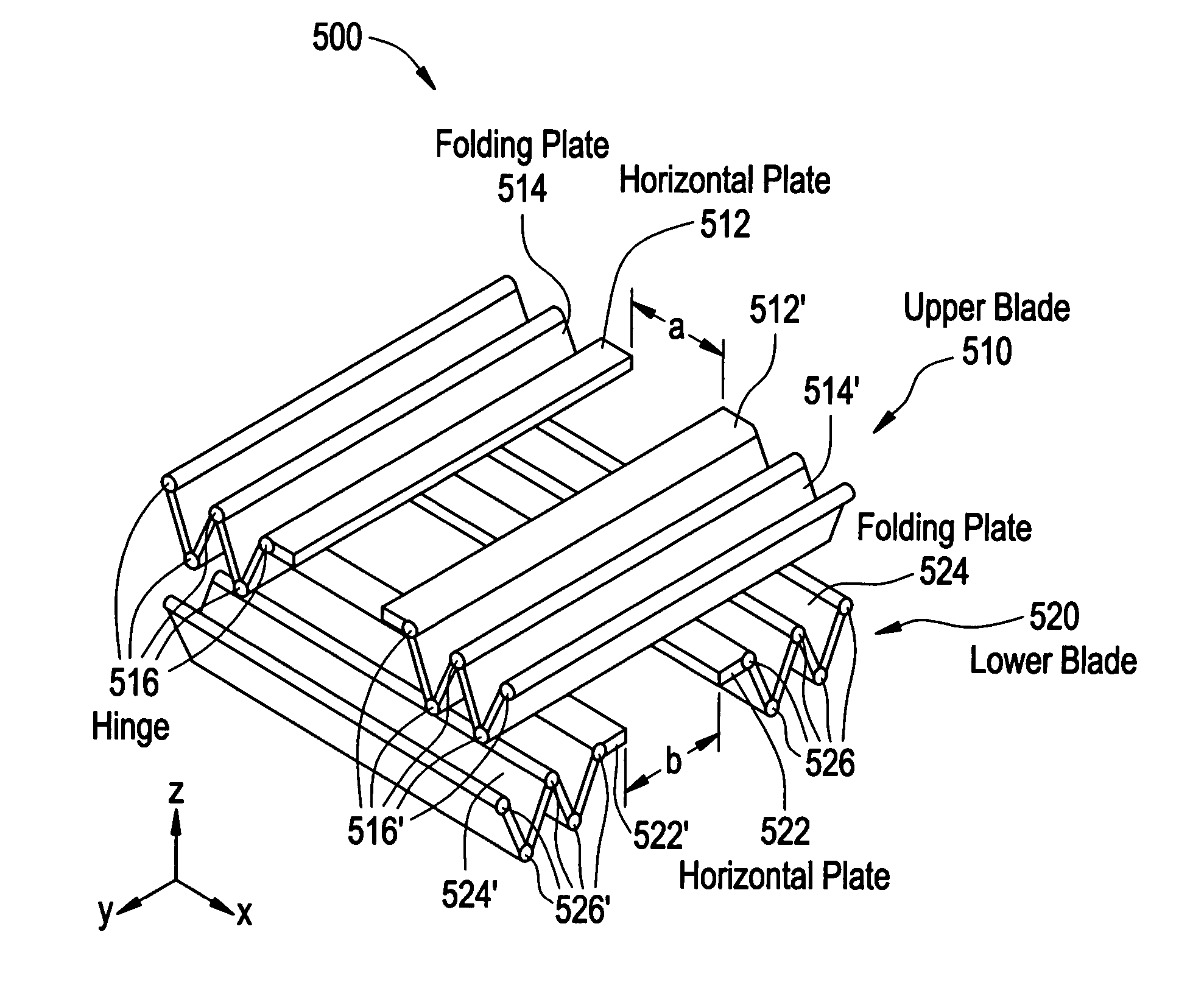
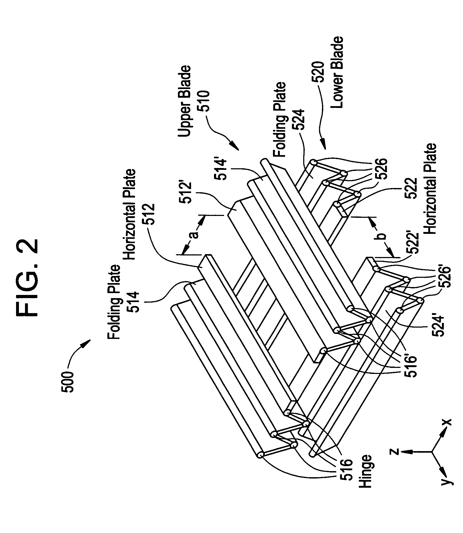
"The present invention provides a collimator that can be reduced in size without sacrificing the aperture and an X-ray irradiator and X-ray apparatus that use the collimator. The collimator comprises a pair of first plate members and a pair of second plate members that can be folded in a zigzag fashion through hinges. The second plate members can be moved independently of the first plate members to increase flexibility in setting the irradiation range. The collimator can be used in an X-ray irradiator or an X-ray apparatus to collimate X-rays and apply them to an object to be radiographed."

Problems solved by technology

In the above conventional collimator there is the problem that a special material which is flexible and superior in X-ray absorbability must be used as the blade material.

Method used


Image

  • Collimator, X-ray irradiator, and X-ray apparatus
  • Collimator, X-ray irradiator, and X-ray apparatus
  • Collimator, X-ray irradiator, and X-ray apparatus

Examples


Embodiment Construction

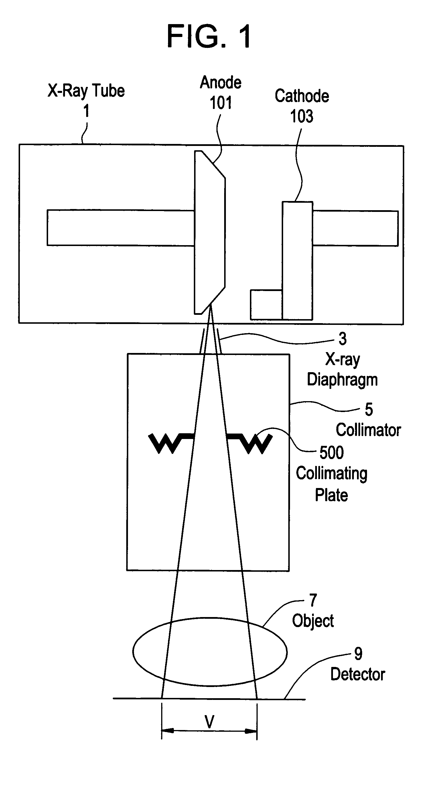
[0022]An embodiment of the present invention will be described in detail hereinunder with reference to the accompanying drawings, provided the invention is not limited to the embodiment. FIG. 1 illustrates a schematic construction of an X-ray apparatus according to an embodiment of the present invention. With the construction of this apparatus, there is shown a working example of the apparatus according to the present invention.

[0023]In the X-ray apparatus, as shown in the same figure, X-ray emitted from an X-ray tube 1 is diaphragmed by an X-ray diaphragm 3 and is collimated by a collimating plate 500 disposed within a collimator 5, then the collimated X-ray is directed to an object 7 to be radiographed and the X-ray which has passed through the object 7 is detected by a detector 9. The X-ray tube 1 is a working example of the X-ray used in the present invention. The collimator 5 is a working example of the collimator used in the present invention. The detector 9 is a working examp...


PUM


Abstract

A collimator comprises a pair of first plate members having X-ray absorbability and a pair of second plate members having X-ray absorbability. The pair of first plate members are movable in a direction parallel to surfaces thereof, and have respective end faces opposed to each other with an X-ray passing aperture being defined by a spacing between the opposed end faces of the first plate members. The pair of second plate members are capable of being folded in a zigzag fashion through hinges, and in order to intercept other X-rays than the X-ray passing through the aperture, each of the second plate members is connected at one end thereof to each end of the first plate members on the side opposite to the opposed end faces of the first plate members and is connected at the other end thereof to each of fixing portions.

Description

CROSS REFERENCE TO RELATED APPLICATIONS[0001]This application claims the benefit of Chinese Application No. 2003-10124810.X filed Nov. 20, 2003.BACKGROUND OF THE INVENTION[0002]The present invention relates to a collimator, an X-ray irradiator, and an X-ray apparatus. Particularly, the present invention is concerned with a collimator for defining an X-ray irradiation range, as well as an X-ray irradiator and an X-ray apparatus both provided with the collimator.[0003]In an X-ray irradiator there is used a collimator for defining an X-ray irradiation range. The collimator has an aperture which permits the passage of X-ray therethrough. The other portion than the aperture of the collimator does not permit the passage of X-ray. The degree of opening of the aperture is changeable, whereby the X-ray irradiation range can be adjusted.[0004]The collimator with such an adjustable aperture has movable plate members, i.e., blades, possessing X-ray absorbability. There are used a pair of blades...

Claims


Application Information

Patent Timeline
Patent Type & Authority Patents(United States)
IPC IPC(8): G21K1/04A61B6/00A61B6/06A61N5/10G03B42/02G21K1/02G21K5/02H01J29/70H05G1/02
CPCG21K1/04
Inventor XU, XIAODONGWANG, XIAOJIEPERRILLAT, DENIS
Owner GE MEDICAL SYSTEMS INC
Learn More