Capping method and capping apparatus

a technology of capping apparatus and capping method, which is applied in the direction of caps, rotating screw stopper insertion, applications, etc., can solve the problems of increasing costs and inability to detect cases, and achieve the effect of reducing costs

Inactive Publication Date: 2006-04-11
SHIBUYA IND CO LTD +1
View PDF12 Cites 26 Cited by
  • Summary
  • Abstract
  • Description
  • Claims
  • Application Information

AI Technical Summary

Benefits of technology

[0009]Accordingly, by determining whether an angle by which the cap actually rotates is within the range of the acceptable angle, a decision as to whether rotational fastening is acceptable can be accurately made in the capper. In addition, since the rotational angle detecting means is merely provided in the capper, costs can be reduced compared to a case where a device for detecting defective rotational fastening is separately provided.

Problems solved by technology

However, the art of the above-cited specification has the problem of being unable to detect a case corresponding to such a defective rotational fastening.
This construction, however, incurs an increase in cost.

Method used


Image

  • Capping method and capping apparatus
  • Capping method and capping apparatus
  • Capping method and capping apparatus

Examples


Embodiment Construction

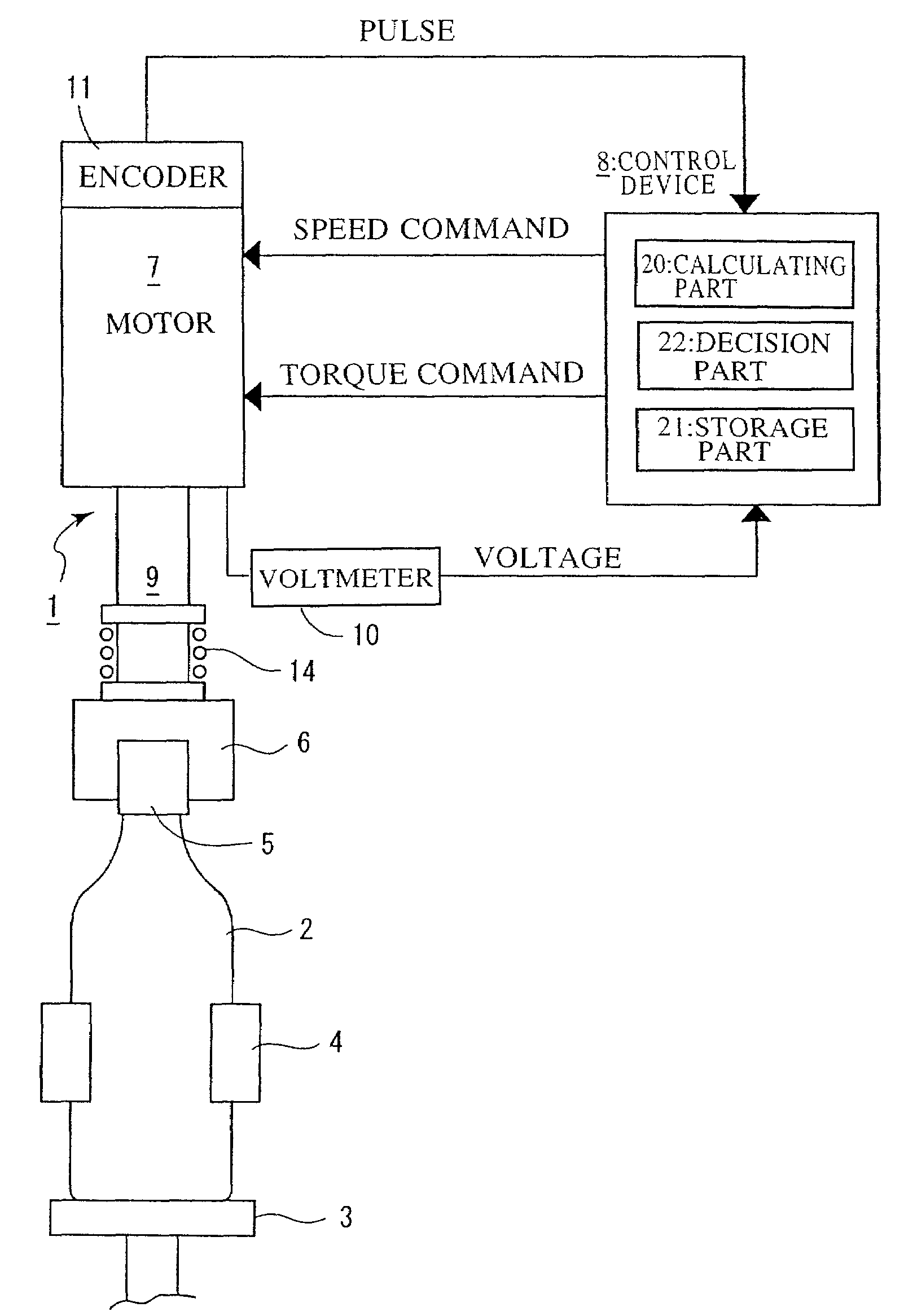
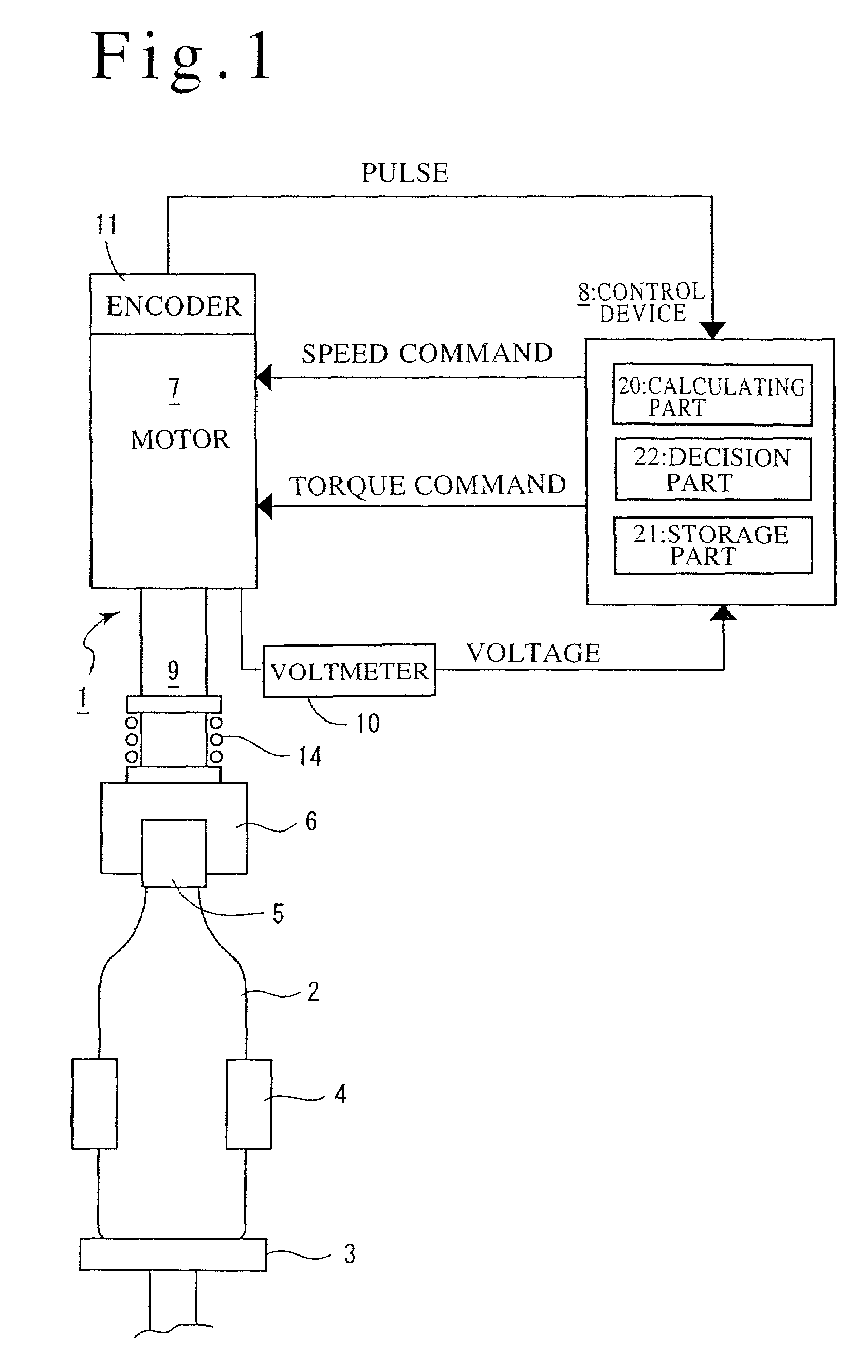
[0016]The invention will be described below with reference to its embodiment shown in the accompanying drawings. In FIG. 1, reference numeral 1 denotes a rotary type of screw capper to which the invention is applied.

[0017]The rotary type screw capper 1 includes carriages 3 (one of which is shown) which are respectively provided at circumferentially equally spaced positions around a rotator (not shown) and on each of which a container 2 is to be placed, grippers 4 (one of which is shown) each of which grips the body portion of the container 2 mounted on the carriages 3, capping heads 6 (one of which is shown) each of which is provided at a position over the carriage 3 to rotationally fasten a cap 5 to the mouth portion of the container 2 gripped by the gripper 4, and a well-known type of lifting cam (not shown) which serves as lifting means for lifting the capping head 6. These capping heads 6 are respectively liftably connected to servo motors 7 via spline shafts 9, and are capable ...


PUM


Abstract

A screw capper 1 includes a capping head 6 which grips a cap 5, a servo motor 7 which rotates the capping head, a voltmeter 10 which measures the torque of the capping head, an encoder 11 which detects the rotational angle of the capping head, and a control device 8 which controls the servo motor. In the screw capper, whether rotational fastening is acceptable is to be determined during the rotational fastening, the measured value of the encoder is measured from a predetermined measurement starting point until a rotational fastening completion point, and if the measured rotational angle is in the range of an acceptable decision angle which is set in advance, it is determined that the rotational fastening has been acceptably performed, whereas if the measured rotational angle is not in the range of the acceptable decision angle, it is determined that the rotational fastening is unacceptable.In the screw capper, defective rotational fastening can be detected, and reductions in costs can be realized compared to a case where a device for detecting such defective rotational fastening is separately provided.

Description

FIELD OF THE INVENTION[0001]The present invention relates to a capping method of and a capper for screwing a cap to a container.DESCRIPTION OF THE PRIOR ART[0002]A capper has heretofore been known which includes a capping head which retains a cap, driving means which rotates this capping head in forward and reverse directions, torque measuring means which measures fastening torque which acts on the cap, and a control device which controls the driving means. The capper monitors the measured value of the torque and completes screwing when the measured value reaches a predetermined rotational fastening torque value. After the screwing has been completed, the capper unfastens the cap to determine a cap-opening torque value, and corrects a fastening torque value to be outputted to the driving means, on the basis of the cap-opening torque value (Japanese Patent Laid-Open No. 229593 / 1993)[0003]In Japanese Patent Laid-Open No. 229593 / 1993, the cap-opening torque value is compared with an ac...

Claims


Application Information

Patent Timeline
Patent Type & Authority Patents(United States)
IPC IPC(8): B65B7/28B67B3/26B67B3/20
CPCB67B3/20B67B3/26B67B3/2093
Inventor TAKEBE, MINORUKASAI, MITSURUYOSHIDA, KENICHIRO
Owner SHIBUYA IND CO LTD
Why Eureka
Try Eureka