Multi-crankshaft, variable-displacement engine

a variable displacement, multi-crank shaft technology, applied in machines/engines, jet propulsion mounting, reconfigurable combination engines, etc., can solve the problems of poor efficiency, relatively poor net fuel economy, and far from optimal powertrain required by the above considerations, so as to reduce the cost and weight of the vehicle, facilitate the transition, and reduce the effect of maintenance costs

Inactive Publication Date: 2006-04-11
ENVIRONMENTAL PROTECTION AGENCY US
View PDF24 Cites 25 Cited by
  • Summary
  • Abstract
  • Description
  • Claims
  • Application Information

AI Technical Summary

Benefits of technology

[0033]This concept of multiple integrated displacement units also appears in U.S. Pat. No. 5,971,092 granted to Walker (1999), which discloses an automotive drivetrain featuring a “split” engine. Although the two parts of the split engine do not reside in a common block, this invention has many features similar to Kronogard's invention. A single cooling system (although not a single lubrication system) is shared by the two engine parts. An overrunning clutch and gearing arrangement allows either engine unit to operate alone, or both units to operate together. Accessories are driven by a direct shaft that is backdriven by the transmission, that is, by transmitting the momentum of the vehicle back through the transmission to power the accessories while the vehicle is in motion. The disclosure cites the ability to provide a single set of accessories as an advantage of the invention. Of course, accessory backdrive is not available while the vehicle is stationary, which presents problems for continuous loads such as the air conditioning compressor, and for intermittent loads such as power steering. The disclosure admits that an auxiliary electric power plant may be necessary to provide power steering and presumably other devices such as air conditioning. The starting means for the two engine units is not mentioned, which suggests that two separate starters would be needed.
[0034]U.S. Pat. No. 6,306,056 B1 granted to Moore (2001) similarly discloses several embodiments of a hybrid automotive powertrain consisting of first and second engine units and an electric motor / generator. In one embodiment of this powertrain, the two engine units are provided in a single block, with a dual parallel crankshaft design similar to that of Kronogard. A designated first primary crankshaft can operate alone, or a secondary crankshaft may operate to supplement the primary crankshaft via a clutching means, to power a single output shaft. Sharing of a single oil pump, water pump, cooling system, lubrication system, air filter, fuel system, engine block, exhaust system, and oil pan are cited as advantages of this integration. To ensure a rapid and smooth transition when additional power is needed, the electric motor / generator portion of the powertrain supplies additional power during the period in which the secondary engine is getting up to speed, after which the secondary engine takes over and the electric motor is returned to its previous status. Although the engine design of Moore arguably provides many advantages over a conventional engine, it has several shortcomings. First, the two engine units will receive uneven wear because the designated primary engine unit will run more frequently than the second unit. This is especially a problem in the integrated, single-block embodiment because worn components would be less accessible for repair. While the components of the first unit could be designed to be more durable than those of the second unit, it may be difficult for like components of varying quality or tolerancing to coexist in a common block while sharing so many support systems. Second, it is not clear how the primary and secondary units may individually be started without requiring two separate starters, which would add cost and weight to the vehicle. Finally, the disclosure makes no mention of how accessories will be driven. Presumably they will be powered directly by the primary engine, or electrically powered by the motor / generator. In the first case, it is not clear how they will continue to receive power when the primary unit is shut off at times of zero or low power demand. In the second case, conventional power drive accessories would have to be replaced by electrically powered versions which are not as well established in the industry. Also see Gray, Jr., et al U.S. Pat. No. 5,495,912.
[0035]In summary, no prior art system provides variable displacement in an automotive powerplant while providing all of the commercially desirable features enumerated above.SUMMARY OF THE INVENTION
[0036]The present invention adopts a variable displacement approach to provide multiple peak power capabilities, and thus multiple peak efficiency ranges, by varying the net volumetric displacement of the power plant. The term “volumetric displacement” refers to the cylinder volume that is swept by a piston in a cylinder as it travels between the extremes of its stroke. The “net volumetric displacement” (NVD) of a multi-cylinder engine is the sum of the volumetric displacements of its cylinders. NVD is a general indicator of engine power because in a naturally aspirated engine it is the controlling factor in the amount of air that can be inducted in each intake cycle, thus controlling the mass of each fuel-air charge, and accordingly the gross energy that is available in each power generating cycle. In a conventional engine, the volumetric displacement of each cylinder, as well as the NVD of the engine, is fixed, which means that the peak power capability and the corresponding range of peak efficiency are also fixed. However, in the present invention the engine possesses more than one peak power capability, and can thus provide a corresponding peak efficiency at each of its power output levels rather than just one.
[0037]Accordingly, the present invention provides an internal combustion engine for a vehicle having variable displacement and including first and second crankshafts mounted within a single unitary engine block. At least two cylinders receiving pistons defining combustion chambers therein are provided for rotatably driving each of the first and second crankshafts by combustion of fuel in the combustion chambers. In one aspect of the present invention, a common output shaft receives power from both of the first and second crankshafts thereby combining the power outputs of the first and second crankshafts to propel the vehicle with the combined power outputs. In this first aspect of the present invention the first and second crankshafts are connected to the common output shaft through respective clutches whereby the common output shaft can be driven either in a first mode by outputs of both of the first and second crankshafts or in a second mode by output of only one of the first and second crankshafts, with the other of the first and second crankshafts isolated from rotation of the output shaft by its associated clutch. The clutches are preferably one-way clutches. This first aspect of the present invention further includes starter gearing independently associated with each of the first and second crankshafts and a starter mounted for selective engagement with the starter gearing of either of the crankshafts.
[0038]In a second aspect the present invention provides an internal combustion engine for a vehicle having variable displacement and including first and second engine crankshafts mounted within a single unitary engine block. As in the first aspect of the present invention, each of the crankshafts is connected to at least two pistons received in respective cylinders and defining combustion chambers therein whereby each crankshaft is rotatably driven by combustion of fuel in the combustion chambers associated with the connected pistons. Also in common with the first aspect, a common output shaft receives torque from both of the first and second crankshafts for powering the vehicle with the combined power outputs. First and second clutches respectfully connect the first and second crankshafts to first and second output gears which drive an input gear fixed on the common output shaft. In the second aspect of the invention an accessory drive for driving accessory systems of the vehicle is driven off of the common output shaft, for example, through an output gear on the common output shaft or through the input gear of the common output shaft.

Problems solved by technology

From an efficiency perspective, the powertrain required by the above considerations is far from optimal.
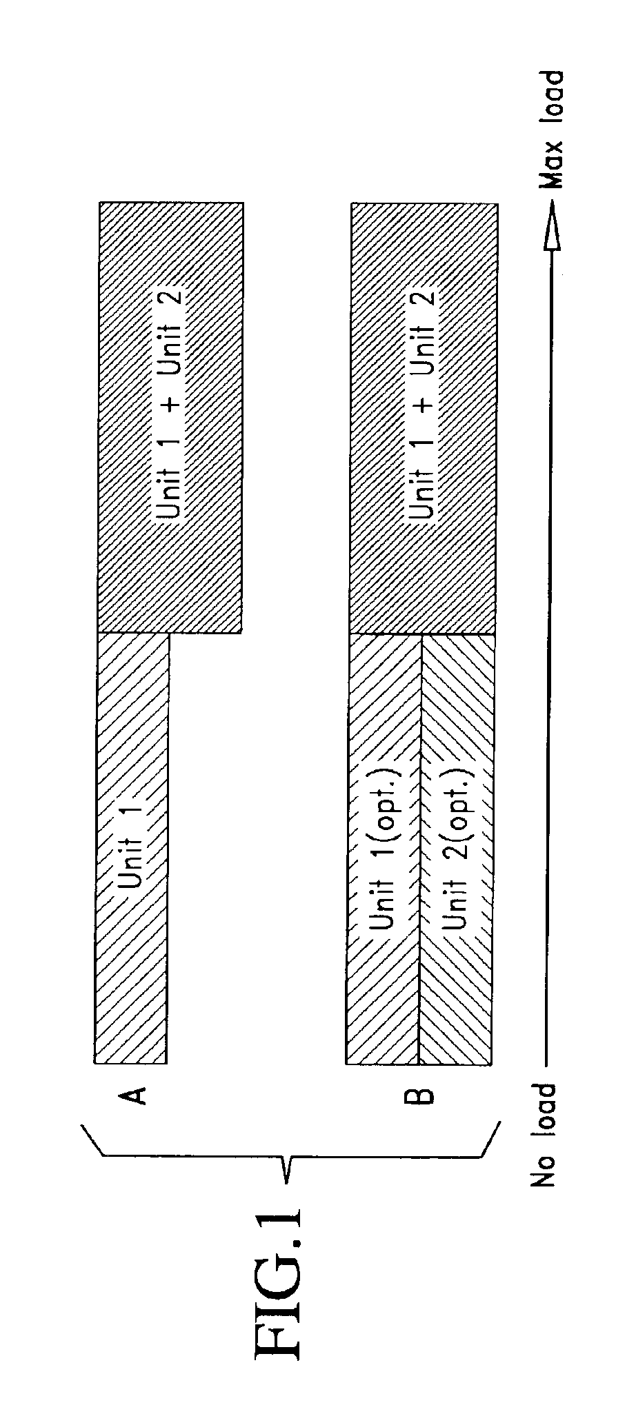
Because an automotive ICE is typically sized to meet the maximum anticipated power demand (which is experienced over only a small fraction of a typical driving cycle), the vast majority of the time it operates at low to moderate power levels where efficiency is relatively poor.
This results in a relatively poor net fuel economy.
However, this would give no capability for meeting peak power demands, leading to unacceptable problems in performance, driver confidence, and safety.
The problem of achieving better automotive energy efficiency in an ICE-powered vehicle can thus be understood as a problem of operating its ICE components at or near their most efficient operating range during the greatest possible portion of the driving cycle, while preserving the ability to meet peak power demands however intermittently they occur.
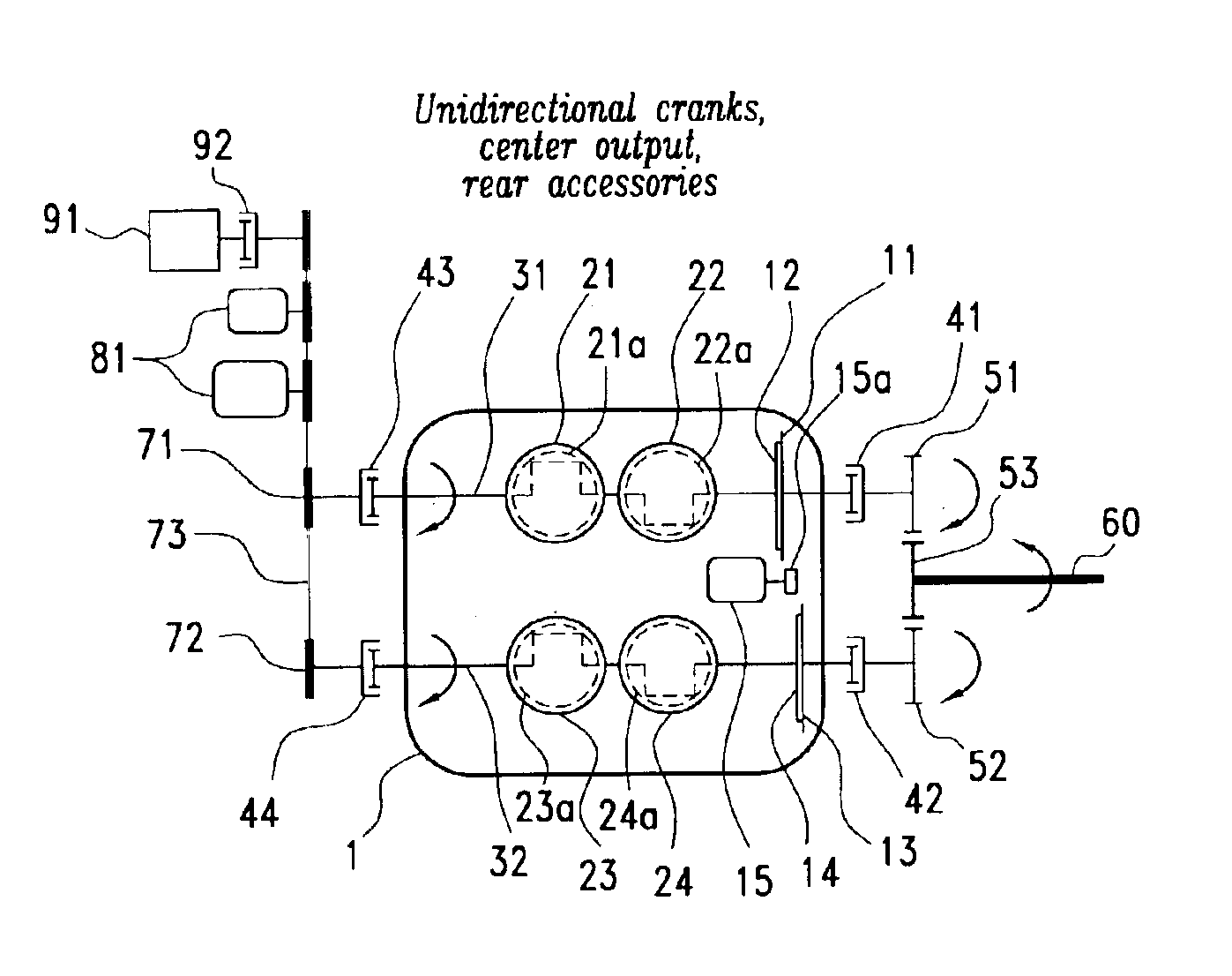
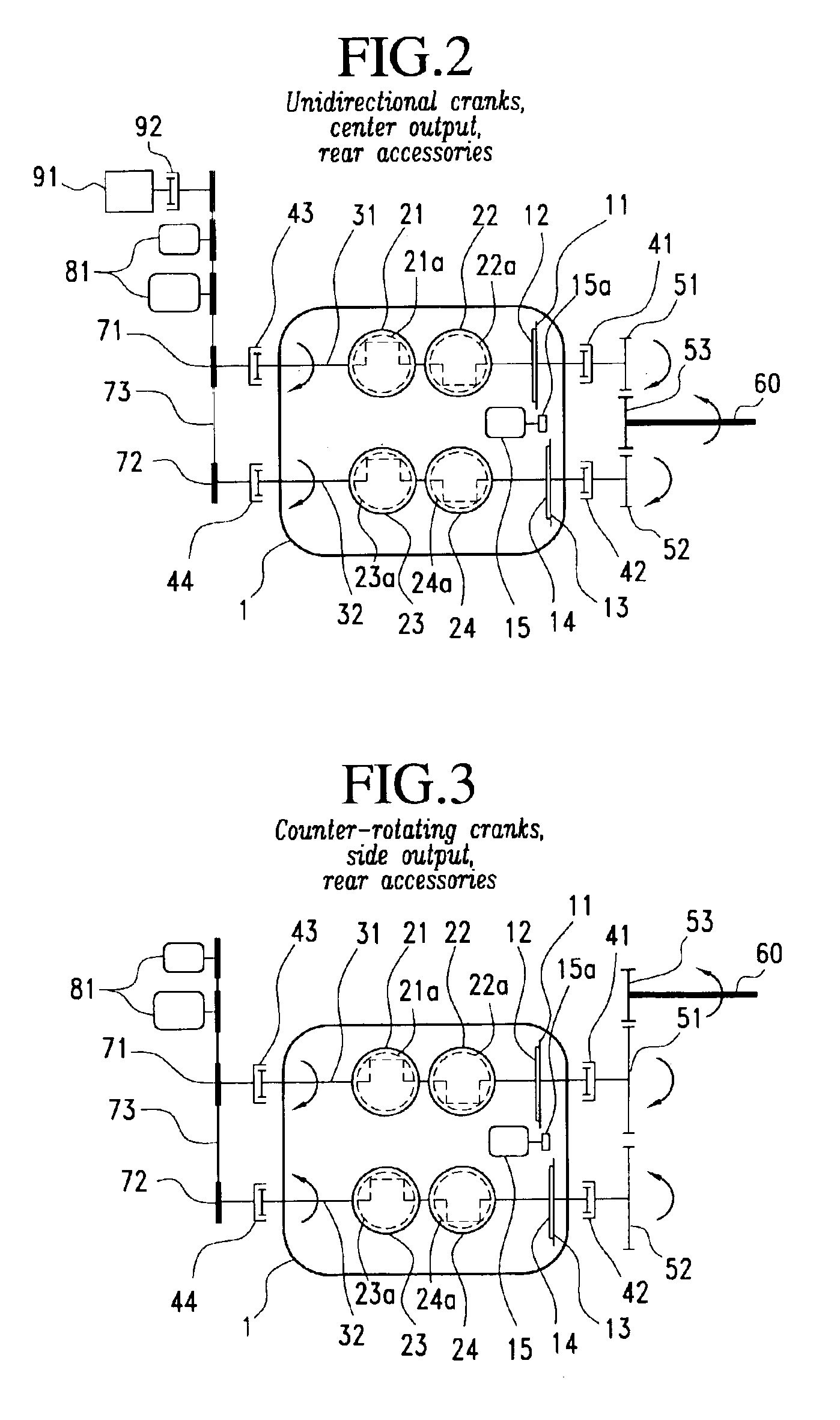
The main shortcoming of designs of this type derives from the fact that all cylinders are connected to a common crankshaft, and so any cylinder that is not in a power producing mode continues to have a piston reciprocating within it, leading to energy losses due to friction and other effects.
This requires a rather complex synchronization means.
Multiple-engine powertrains such as described above present several engineering difficulties that limit their practicality in automotive applications.
The need to frequently start and stop the engines is one difficulty.
Conventional ICEs employed in such a system would encounter significant efficiency losses and increased emissions as a result of frequent restarting.
Driver confidence might also be negatively influenced if the driver perceives the frequent starting and stopping of the engines as a reliability risk.
Accessories present another difficulty because conventional accessories are powered by direct engine power, meaning that at least one engine capable of driving accessories must always be running.
This is especially problematic in certain hybrid vehicle applications, in which there may be times when no engine power is needed at all, in which case accessories would have to be driven by a different power source entirely.
The method of operation of the power plant is also critical.
For example, a method of operation that requires one engine to run more frequently or to routinely experience greater loads might cause it to wear out faster and increase the frequency of trips to the repair shop.
The inertia of the moving vehicle may alternatively be employed to start an offline engine, but inertia is not available if the vehicle is at a stop.
This precludes some promising operating strategies that would call for more flexibility.
While each displacement unit could be supplied with its own set of power drive accessories so that the needs of the vehicle may be met whenever either unit is operating, this would add weight, cost, and complexity to the vehicle.
Therefore, rapidly starting the second displacement unit in a manner that does not affect the motion of the vehicle or reduce the available power is critical.
Although all of these inventions do possess multiple crankshafts, none of them achieve variable displacement.
Similarly, the housing of multiple crankshafts in a common engine block is not new.
However, there is a limited amount of prior art that does have some of these elements in a variable displacement power plant.
However, there is no mention of how the individual piston / crankshaft subsystems may be started by a single starter, nor any mention of how vehicle accessories may be driven while one or the other crankshaft is offline.
Of course, accessory backdrive is not available while the vehicle is stationary, which presents problems for continuous loads such as the air conditioning compressor, and for intermittent loads such as power steering.
First, the two engine units will receive uneven wear because the designated primary engine unit will run more frequently than the second unit.
This is especially a problem in the integrated, single-block embodiment because worn components would be less accessible for repair.
While the components of the first unit could be designed to be more durable than those of the second unit, it may be difficult for like components of varying quality or tolerancing to coexist in a common block while sharing so many support systems.
Second, it is not clear how the primary and secondary units may individually be started without requiring two separate starters, which would add cost and weight to the vehicle.
In the second case, conventional power drive accessories would have to be replaced by electrically powered versions which are not as well established in the industry.
In summary, no prior art system provides variable displacement in an automotive powerplant while providing all of the commercially desirable features enumerated above.

Method used


Image

  • Multi-crankshaft, variable-displacement engine
  • Multi-crankshaft, variable-displacement engine
  • Multi-crankshaft, variable-displacement engine

Examples


Embodiment Construction

[0069]All of the preferred embodiments shown in the drawing figures and described in the ensuing discussion illustrate a pair of two-cylinder displacement units in a parallel arrangement for the purpose of clarity, with the realization that more than two displacement units, more or less than two cylinders per unit, and / or such units disposed in a series arrangement rather than a parallel arrangement, could equally well be employed within the scope of the invention.

[0070]FIG. 1 illustrates two different operating strategies, termed “A” and “B”. According to operating strategy “A”, a primary displacement unit “Unit 1” operates alone to power the vehicle when power demand is low to moderate. When power demand increases past a predetermined level (either a fixed level or a computed level based on operating conditions), “Unit 2” which is designated as a secondary unit begins operating to supplement the power of Unit 1. When the power demand once again drops below the predetermined level,...


PUM


Abstract

An internal combustion engine for a vehicle provides variable displacement by selectively driving one or more engine crankshafts mounted within a single unitary engine block. In several embodiments the crankshafts are connected to a common output shaft with a one-way clutch between the common output shaft and at least one of the crankshafts. In one aspect starter gearing is independently associated with each of the first and second crankshafts and a starter is provided for selective engagement with the starter gearing of either of the crankshafts. In another aspect, an accessory drive for driving accessory systems of the vehicle receives power from any crankshaft which is operating, yet is isolated from any crankshaft that is not operating by a one-way clutch.

Description

BACKGROUND OF THE INVENTION[0001]1. Field of the Invention[0002]The general field of application is internal combustion engines, particularly internal combustion engines for automotive use. More specifically, the invention relates to variable displacement in an internal combustion power plant.[0003]2. The Prior Art[0004]The growing utilization of automobiles greatly adds to the atmospheric presence of various pollutants including oxides of nitrogen and greenhouse gases such as carbon dioxide. Accordingly, new approaches to significantly improving the efficiency of fuel utilization for automotive powertrains are needed.[0005]In most current automotive powertrain designs, an internal combustion engine (ICE) is employed as the source of motive power. The average power demanded in normal driving is quite small, but intermittent events such as rapid acceleration, passing, trailer towing, and hill climbing demand power far in excess of the average demand. Because the ICE must respond in r...

Claims


Application Information

Patent Timeline
Patent Type & Authority Patents(United States)
IPC IPC(8): F01B21/04F02B73/00
CPCF02B73/00B60K5/08
Inventor GRAY JR., CHARLES L.
Owner ENVIRONMENTAL PROTECTION AGENCY US
Why Eureka
Try Eureka