Wire bonding method

a wire bonding and wire technology, applied in the field of wire bonding methods, can solve the problems of the method of the japanese patent application laid-open (kokai), the inability to prevent contact between the wire and the circuit board, and the inability to ensure the inclination and flat surface of the joining of the wire and bump, so as to improve the reliability of the bonding joint and ensure the stability of the wire loop

Inactive Publication Date: 2006-04-11
SHINKAWA CO LTD
View PDF5 Cites 9 Cited by
  • Summary
  • Abstract
  • Description
  • Claims
  • Application Information

AI Technical Summary

Benefits of technology

[0010]The object of the present invention is to provide a wire bonding method which that forms a sufficiently wide inclined wedge on a bump, thus obtaining an improved reliability of the bonding joint and a stable wire loop.

Problems solved by technology

The method of the Japanese Patent Application Laid-Open (Kokai) No. 10-112471 has problems.
Furthermore, although the generation of a wire tail can be suppressed by forming the wedge bonding after bump formation in a shape that is bent toward the rear, a sufficient inclination and flat surface cannot be ensured in the joining of the wire and bump.
Accordingly, contact between the wire and circuit board and contact between the wire and wiring following the joining of the bump and wire cannot be prevented.
A narrow surface area on the inclined wedge causes unreliable bonding, and the secondarily bonded wire can be easily bent.
Thus, a stable wire loop is not obtainable.

Method used


Image

  • Wire bonding method
  • Wire bonding method
  • Wire bonding method

Examples


Embodiment Construction

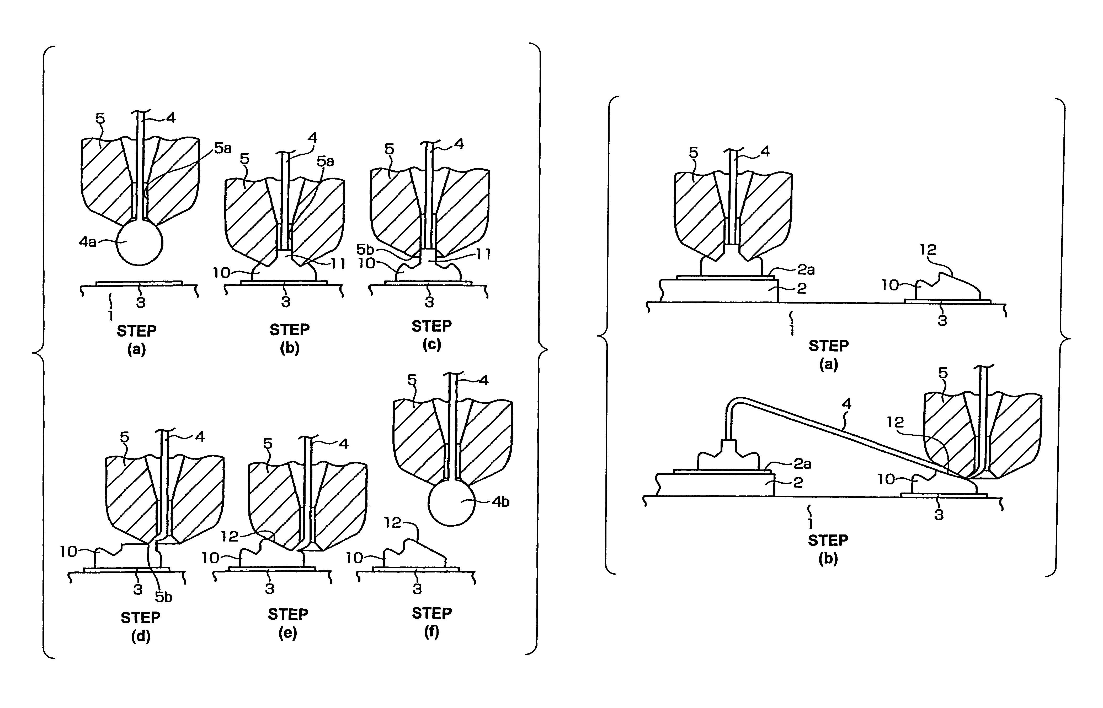
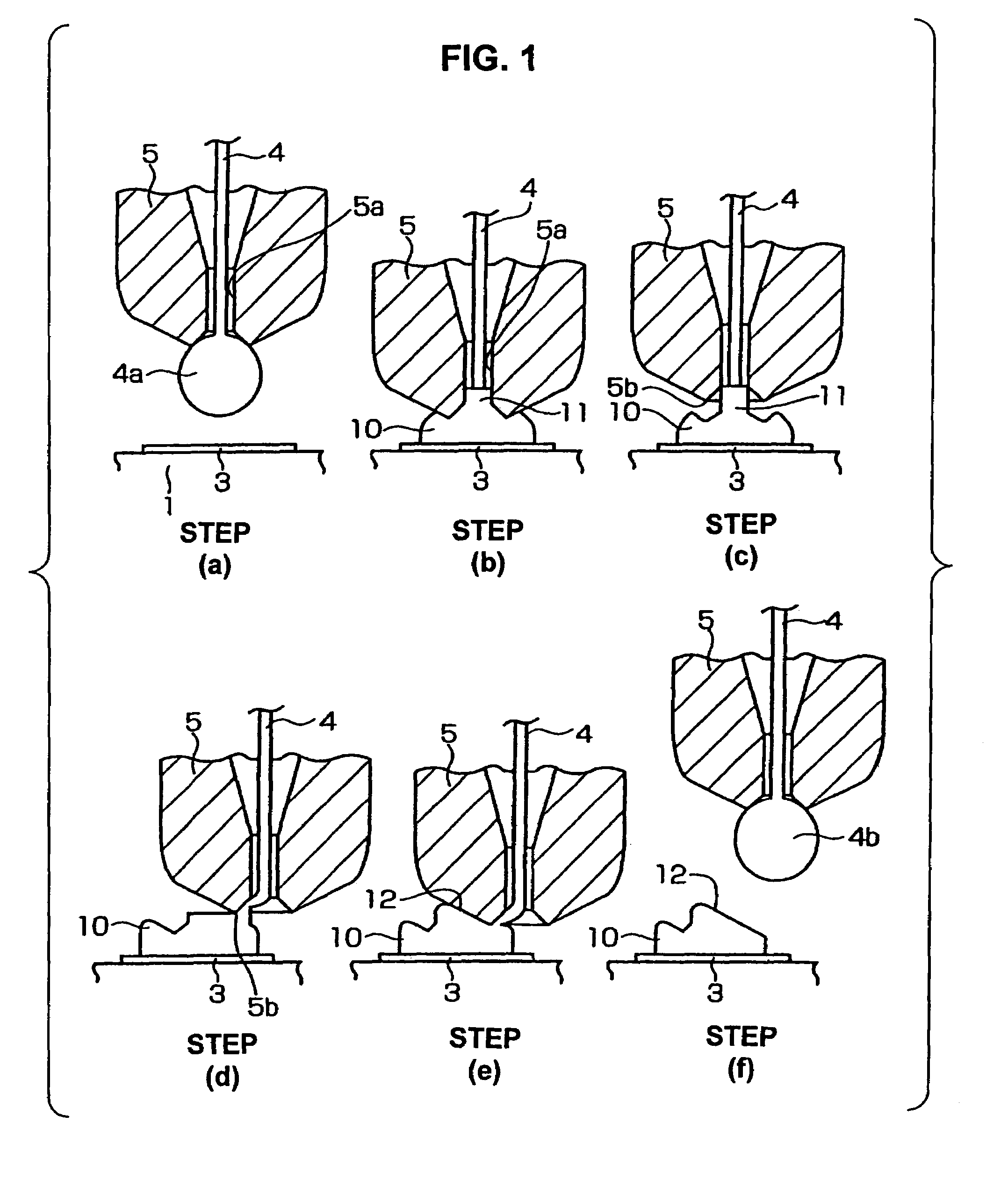
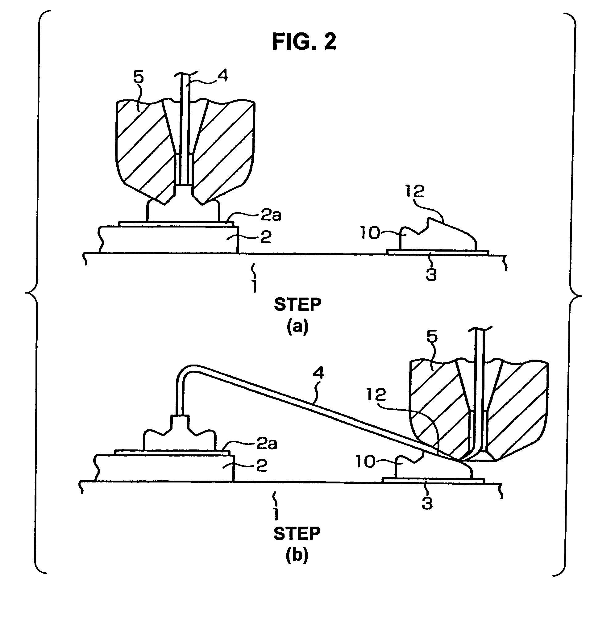
[0015]The wire bonding method of one embodiment of the present invention will be described below with reference to FIGS. 1 and FIG. 2. In FIG. 2, the step (b) shows the completed state of wire bonding between a die and wiring performed using the wire bonding method of one embodiment of the present invention.

[0016]As seen from the step (b) in FIG. 2, a die 2 on which a pad 2a is formed is mounted on a circuit board 1 which is a substrate such as a ceramic substrate, printed substrate, etc. or is a lead frame, etc. Wiring 3 is formed on the circuit board 1. A bump 10 is formed on the wiring 3, and a wire 4 is connected between the pad 2a and bump 10. The reference numeral 5 is a capillary through which the wire 4 passes.

[0017]The wire bonding shown in completed step (b) in FIG. 2 is obtained by the steps described below.

[0018]First, as shown in step (a) of FIG. 1, a ball 4a is formed by an electric torch (not shown) on the tip end of the wire 4 that passes through the through-hole 5a ...


PUM

PropertyMeasurementUnit
heightaaaaaaaaaa
surface areaaaaaaaaaaa

Abstract

A wire bonding method including the steps of forming a bump by performing ball bonding of a ball by wire on a second conductor, raising a capillary to a height that is equal to or lower than the height of a ball portion that rises into a through-hole of the capillary during formation of the bump, moving the capillary in a direction that is opposite from the first conductor, lowering the capillary so as to form an inclined wedge on the bump, cutting the wire, performing the primary bonding on the first conductor, and making a loop with the wire with respect to the bump from the first conductor, thus performing the secondary bonding on the inclined wedge on the bump.

Description

BACKGROUND OF THE INVENTION[0001]1. Field of the Invention[0002]The present invention relates to a wire bonding method that performs wire bonding between two conductors.[0003]2. Prior Art[0004]Japanese Patent Application Laid-Open (Kokai) Nos. 10-112471 and 2002-280410 disclose wire bonding methods that connect a wire between a first conductor and a bump on a second conductor after such a bump is formed on the second conductor.[0005]In Japanese Patent Application Laid-Open (Kokai) No. 10-112471, a bump is formed by performing ball bonding on the second conductor; and after wedge bonding is performed on the opposite side of the bump from the first conductor, primary bonding is performed on the first conductor. Then, the wire is looped from the first conductor side with respect to the bump, and secondary bonding is performed on the bump.[0006]In Japanese Patent Application Laid-Open (Kokai) No. 2002-280410, after a bump has been formed by performing, using a bonding wire, ball bonding...

Claims


Application Information

Patent Timeline
Patent Type & Authority Patents(United States)
IPC IPC(8): B23K31/02B23K20/00H01L21/60
CPCB23K20/004H01L24/78H01L24/85H01L24/48H01L2924/01033H01L2224/0401H01L2224/05599H01L2224/48091H01L2224/48227H01L2224/48465H01L2224/48471H01L2224/48479H01L2224/4848H01L2224/78301H01L2224/85045H01L2224/85051H01L2224/85181H01L2224/85186H01L2224/85399H01L2224/85986H01L2924/01004H01L2924/01005H01L2924/01006H01L2924/01082H01L2924/00014H01L2224/45099H01L2924/00H01L2924/15787H01L2224/4554A01K13/001A46B9/04
Inventor MII, TATSUNARIWATANABE, HIROSHI
Owner SHINKAWA CO LTD
Why Eureka
Try Eureka