
Method and device for correcting in-vivo sensor drift

a sensor and in-vivo technology, applied in the field of in-vivo sensor drift correction, can solve the problems of micro-manometers and fiber optic sensors being prone to the problem of signal drift, hydrostatic coupling transducers are vulnerable to motion artifacts, and failures to achieve the effect of detecting motion artifacts

Active Publication Date: 2006-04-11
DATASCOPE
View PDF8 Cites 43 Cited by
  • Summary
  • Abstract
  • Description
  • Claims
  • Application Information

AI Technical Summary

Problems solved by technology

Unfortunately, hydraulically coupled transducers are vulnerable to motion artifact.
Inflation and deflation of the IAB balloon membrane causes movement of the IAB catheter, which generates inertial forces in the fluid and pressure transducer coupled to it, resulting in artifact.
Another disadvantage of the traditional transducer configuration is that it requires the use of a separate inner lumen to couple the transducer to the tip of the IAB catheter.
These attempts have proven to be unsuccessful because the device is prone to signal drift and is susceptible to interference from electro-surgical units.
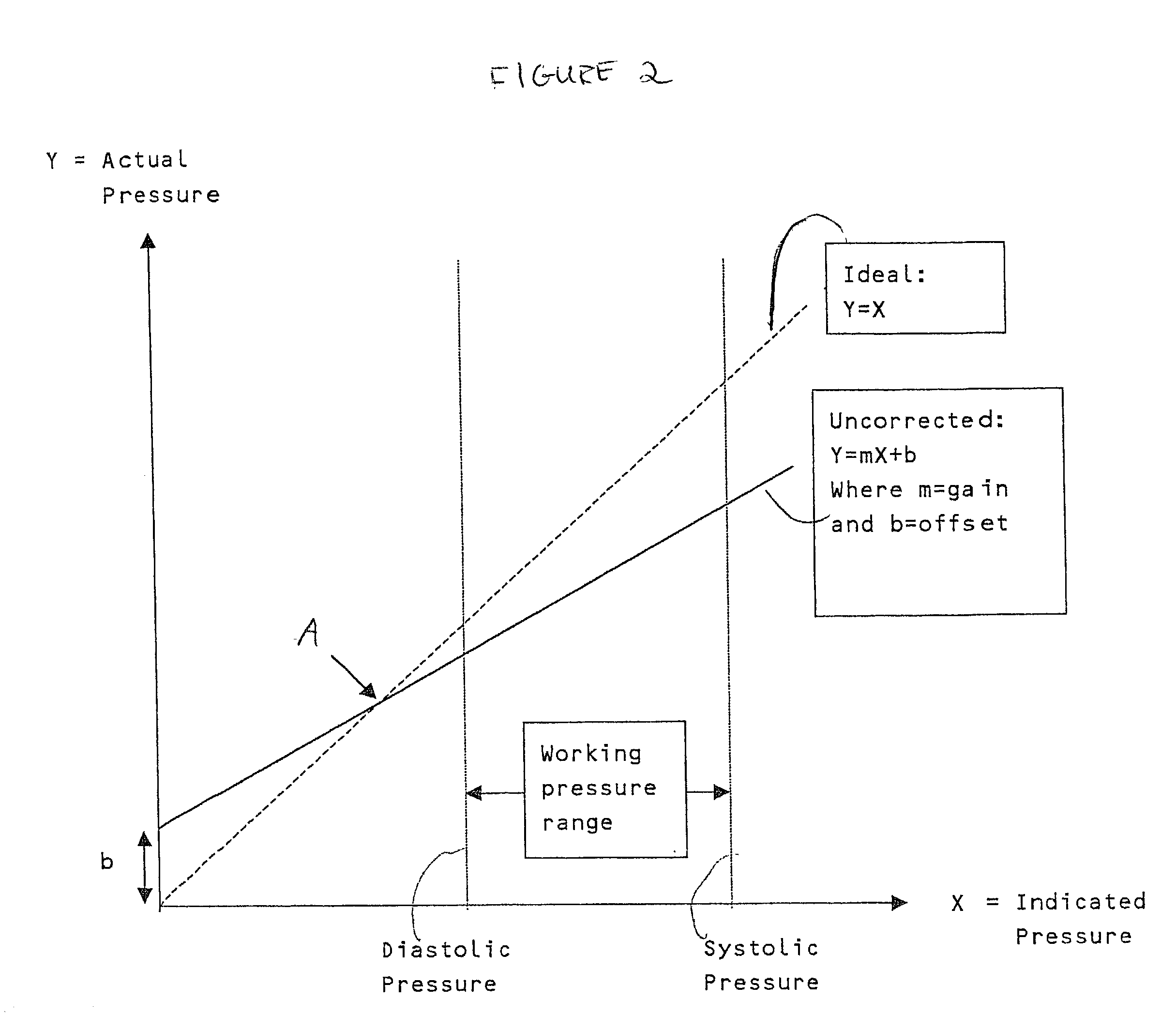
Unfortunately, both micro-manometers and fiber optic sensors are prone to the problem of signal drift.
In addition, the adhesive bonds which couple the diaphragm to the reference chamber may result in a change in stiffness, causing a change in the sensitivity of the device to pressure.
Finally, the interface electronics, which convert the optical signal to an electrical signal can be prone to both gain and offset drift.
The Kanai method for addressing the problem of drift has a significant disadvantage.
Namely, Kanai attempts to correct for offset at a defacto calibration point at mean blood pressure, and thus, does not completely eliminate the drift error.
Furthermore, Kanai completely ignores the gain shift problem, which may also significantly contribute to signal drift and results in a loss of accuracy.
Kanai's method for reducing zero point drift is also faulty because an inaccurate method is used to compute mean pressure.
These features are likely to be corrupted when they are measured, via the IAB membrane, by the shuttle gas transducer.
The Millar device suffers from a number of drawbacks.
Firstly, Millar does not correct for errors in the micro-manometer's gain or drift in gain.
If the gain is not corrected, then the amplitude of the displayed pulse will be in error.
The fidelity of the pressure waveform can be corrupted if the filters or methods used to extract the AC signals from the micromanometer and the DC (mean pressure) signal from the secondary source are not coordinated.
However, Millar requires that the process extract only the mean pressure.

Method used


Image

  • Method and device for correcting in-vivo sensor drift
  • Method and device for correcting in-vivo sensor drift
  • Method and device for correcting in-vivo sensor drift

Examples


Embodiment Construction

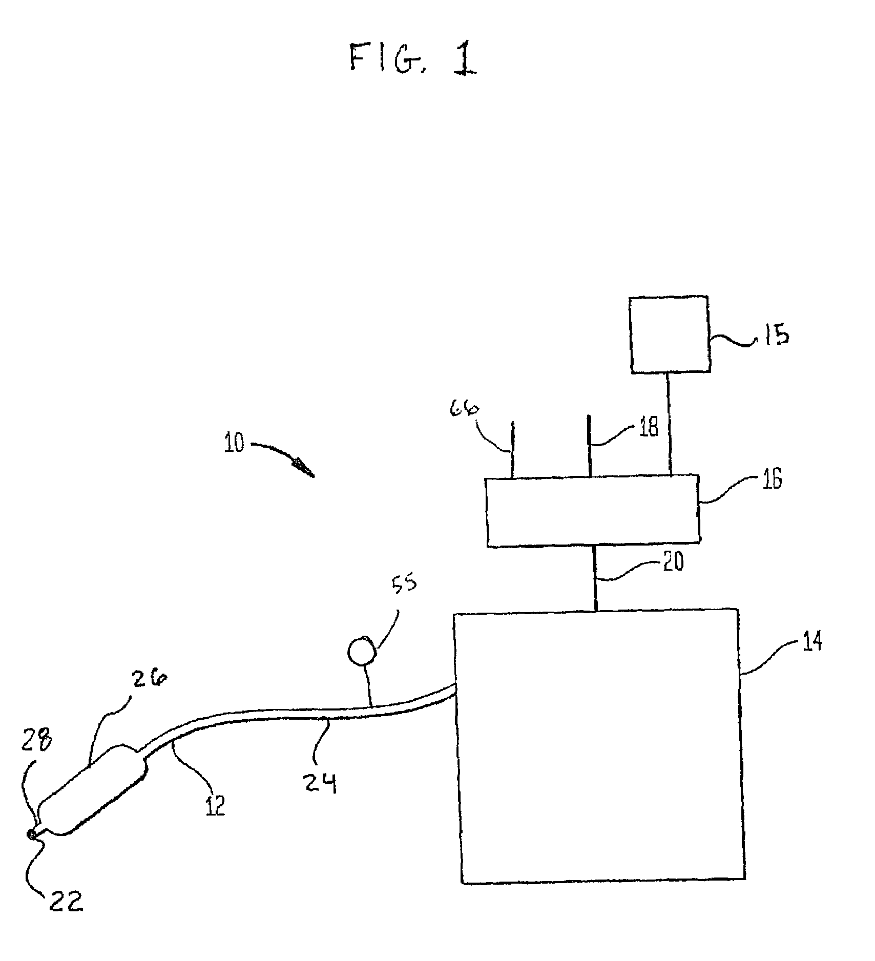
[0041]The details of the invention are explained below as used with an intra-aortic balloon (IAB) catheter system. However, the present invention may be used to remedy the signal drift problem with any catheter-based system having an in-dwelling sensor of any kind and a second source for calibrated measurement.

[0042]It is well known in the art, as described in, for example, the specification of U.S. Pat. No. 4,362,150, to provide cardiac assistance by introducing a balloon into the thoracic aorta of a patient and causing the balloon to inflate and deflate in anti-phase with the contraction of the patient's heart. A balloon of this type is inflated at the beginning of diastole, in order to increase the blood flow to the coronary and carotid arteries. The balloon is then deflated just prior to the start of systole, in order to reduce the load on the left ventricle. IAB therapy increases coronary artery perfusion, decreases the workload of the left ventricle, and allows healing of the ...


PUM


Abstract

A method and device for reducing signal drift on a balloon catheter mounted pressure sensor by adjusting for signal gain and / or zero offset, and by separately calibrating the constant signal component and the time-varying signal component of an uncalibrated source signal to produce a calibrated source signal.

Description

BACKGROUND OF THE INVENTION[0001]1. Field of the Invention[0002]The invention relates to an intra-aortic balloon pump system. More particularly, the invention relates to a method and device for accurately measuring arterial blood pressure via a pressure sensor on an intra-aortic balloon catheter.[0003]2. Description of the Prior Art[0004]A key function of many catheters is that of continuously monitoring blood pressure. In many cases, this process must provide accurate measurement of the blood pressure waveform's high frequency components. For example, reliable detection of the dicrotic notch of the aortic blood pressure waveform typically requires a pressure signal having a bandwidth of 15 Hz or better. Detection of the dicrotic notch is generally used for the inflation / deflation timing of an intra-aortic balloon (“TAB”) catheter.[0005]Conventional TAB catheter invasive pressure monitoring is performed with low cost piezo resistive transducers, which are hydraulically coupled to th...

Claims


Application Information

Patent Timeline
IPC IPC(8): A61N1/362A61B5/0215
CPCA61B1/00082G01L27/002A61B5/02156
Inventor WILLIAMS, JONATHAN
Owner DATASCOPE
Learn More