

Optical filter and process for producing the same
a technology of optical filters and filters, applied in the field of optical filters, can solve the problems of shortening the service life of optical filters, deteriorating environmental resistance of these conventional optical filters, and accelerating devitrification, so as to improve the stability of monomer compositions and increase the transparency of polymers
- Summary
- Abstract
- Description
- Claims
- Application Information
AI Technical Summary
Benefits of technology
Problems solved by technology
Method used
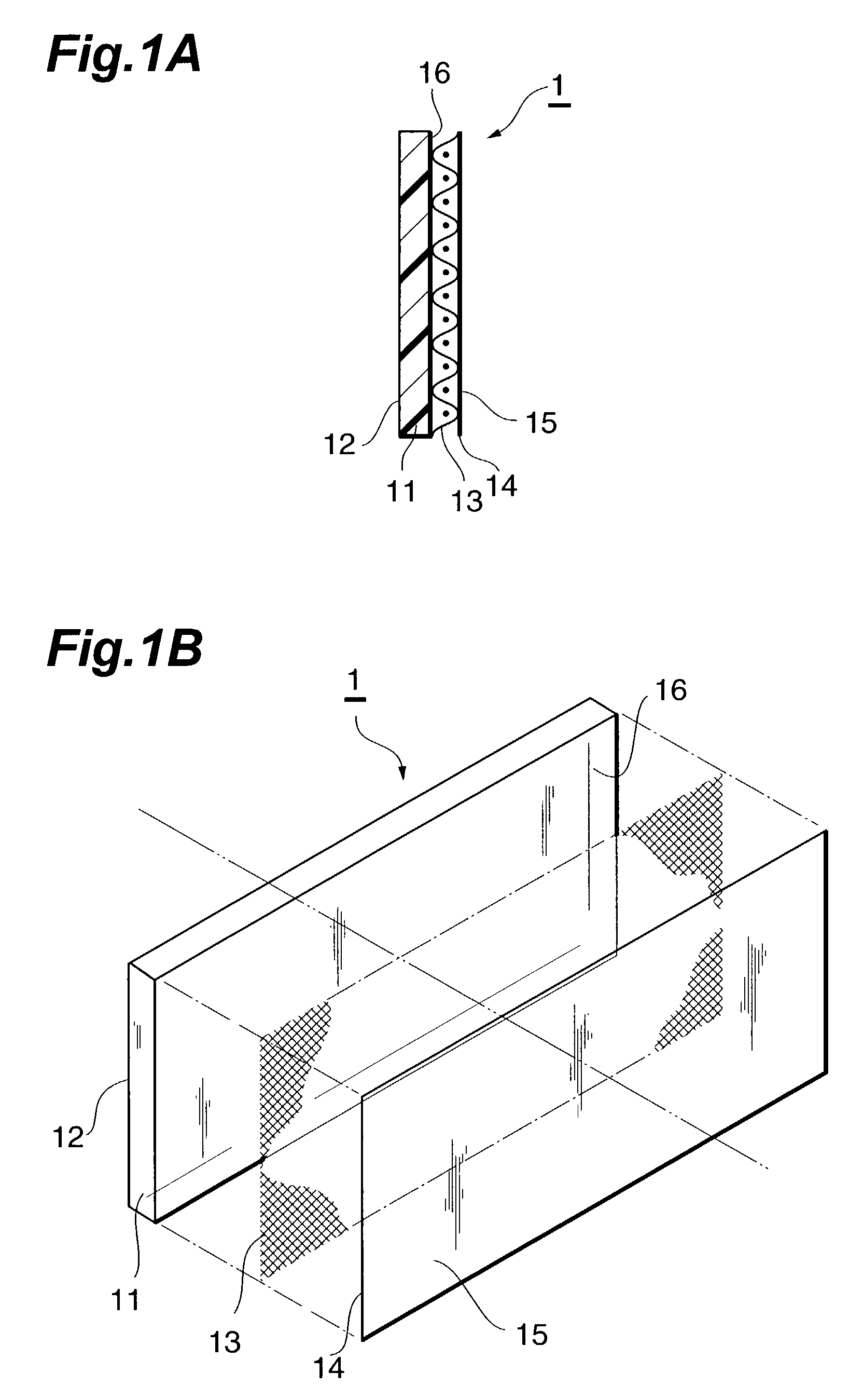
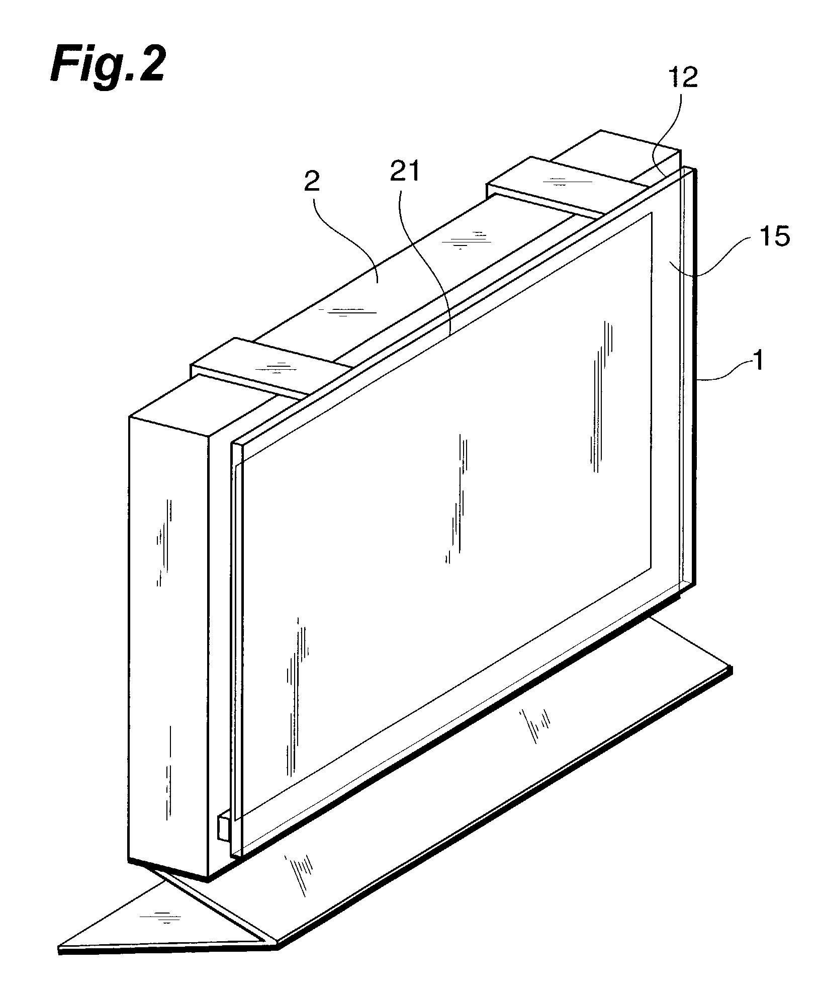
Image

Examples
example 1
[0207](1) A monomer solution was obtained by mixing 16 g of the phosphoric ester compound expressed by Formula (28)-s (hereinafter referred to as “phosphoric ester A”), 14.4 g of the phosphoric ester compound expressed by Formula (28)-t (hereinafter referred to as “phosphoric ester B”), 20 g of diethylene glycol dimethacrylate, 48.6 g of methyl methacrylate, and 0.9 g of α-methylstyrene.
[0208](2) 32 g of copper benzoate (cupric benzoate; the same applies hereinafter) was added to and dissolved in this monomer solution, after which this solution was left for 24 hours in a −20° C. refrigerator to crystallize and precipitate the benzoic acid (melting point: 122° C.)
[0209](3) The precipitated benzoic acid was filtered off the monomer solution at an environment temperature of −20° C.
[0210](4) 2.0 g of tert-butyl peroctanoate was added as a polymerization initiator to this monomer solution. This monomer solution was poured into a polymerization cell comprising two glass sheets and a PVC g...
example 2
[0212]Other than using 17.3 g of phosphoric ester A, 15 g of phosphoric ester B, and 46.7 g of methyl methacrylate, a light blue, transparent optical filter in the form of a sheet 0.5 mm thick was obtained in the same manner as in Example 1 above. The P / Cu molar ratio of this optical filter was 1.20. The copper ion content in the optical filter was 6.1 wt %.
example 3
[0213]Other than adding 0.7 g of water to the monomer solution, a light blue, transparent optical filter in the form of a sheet 0.5 mm thick was obtained in the same manner as in Example 2 above. The P / Cu molar ratio of this optical filter was 1.20. The copper ion content in the optical filter was 6.1 wt %.
PUM
| Property | Measurement | Unit |
|---|---|---|
| /Cu molar ratio | aaaaa | aaaaa |
| molar ratio | aaaaa | aaaaa |
| P/Cu molar ratio | aaaaa | aaaaa |
Abstract
Description
Claims
Application Information