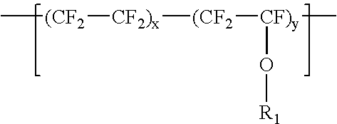
Polyimide based compositions useful as electronic substrates, derived in part from (micro-powder) fluoropolymer, and methods and compositions relating thereto

a technology of polyimide and composition, applied in the direction of non-metallic protective coating application, coupling device connection, synthetic resin layered product, etc., can solve the problems of reducing product consistency and mechanical performance, and affecting the effect of chemical composition

Inactive Publication Date: 2006-04-11
EI DU PONT DE NEMOURS & CO
View PDF11 Cites 65 Cited by
  • Summary
  • Abstract
  • Description
  • Claims
  • Application Information

AI Technical Summary

Benefits of technology

[0010]ii. by processing the composition at a temperature above the fluoropolymer softening point, causing it to be more flowable or semi-flowable, and thereby better enabling the lower surface energy fluoropolymer component (in comparison to the relatively higher surface energy polyamic acid or polyimide component) to reach a more thermodynamically preferred state at the surface of the blend (generally speaking, lower surface energy components tend to bloom to the surface when mixed with higher surface energy components, where migration between the two components is possible).

Problems solved by technology

However, such compositions can be problematic, due to incompatibility between one or more polymeric components.
Such incompatibility can create undesirable voids, due to separation between incompatible polymeric components, and such separation can diminish product consistency and mechanical performance, while (undesirably) increasing water absorption properties.

Method used


Image

  • Polyimide based compositions useful as electronic substrates, derived in part from (micro-powder) fluoropolymer, and methods and compositions relating thereto
  • Polyimide based compositions useful as electronic substrates, derived in part from (micro-powder) fluoropolymer, and methods and compositions relating thereto
  • Polyimide based compositions useful as electronic substrates, derived in part from (micro-powder) fluoropolymer, and methods and compositions relating thereto

Examples


examples 1 – 5

EXAMPLES 1–5

[0230]A slurry was prepared consisting of three components, a polyamic acid, a fluoropolymer micro powder and a polar solvent. 40 grams of dimethylacetamide solvent was added to a blender. ZONYL® Micronized Powder was hammer milled and sieved through both a 325 and 400-mesh screen filter to form micro powder derived from MP-1600. After the MP-1600 in “micro powder” was formed, 10 grams were weighted and added to the blender containing the solvent. The blender was started at low speed for 1 minute then increased to high speed for an additional minute. Ten grams of a 20 weight percent polyamic acid solution, dissolved in dimethylacetamide, was added to the blender and stirred for one minute. The polyamic acid solution was derived from a diamine and a dianhydride. In this case, the diamine was 4,4′-ODA and the dianhydride was PMDA.

[0231]Next, a high-viscosity polyamic acid solution was prepared using the same two monomers. First, a low-viscosity polyamic acid (about 50 pois...

examples 6 – 10

EXAMPLES 6–10

[0238]EXAMPLES 6–10 were prepared in accordance with EXAMPLES 1–5. However, in these EXAMPLES, the fluoropolymer resin micro powder was derived from ZONYL® MP-1100 instead of MP-1600.

[0239]MP-1100 is a lower molecular weight “micronized” powder compared to MP-1600. Again, the polyamic acid prepared for both the fluoropolymer slurry and the high-viscosity polyamic acid was derived from substantially equimolar amounts of 4,4′-ODA and PMDA. The portions are described in Table 3.

[0240]

TABLE 3Fluoropolymer micro-powder fillerloading and material balance sheetFinalPolyamicFilm Conc.AcidLoading ofSlurry Portion Breakdown20 weightfluoropolymerMicro powder20 weightpercentmicro powderderived from% polyamic highin polyimideZONYL ®acid from viscosity(wt. %)MP-1100 (g)DMAc (g)slurry (g)acid (g)20 (E-6)10401019030 (E-7)17.268.61019040 (E-8)26.7106.71019050 (E-9)401601019060 (E-10)6024010190

The following results were measured for EXAMPLES 6–10.

[0241]

TABLE 4Selected properties of PMDA / ...

examples 11 – 17

EXAMPLES 11–17

[0242]EXAMPLES 11–17 were prepared in accordance with EXAMPLES 1–5, however the monomers used to prepare the high-viscosity polyamic acid were altered. Instead of using and equimolar ratio of 4,4′-ODA and PMDA, three monomers were used.

[0243]In these EXAMPLES, a mixture of pyromellitic dianhydride (PMDA) and oxydiphthalic anhydride (ODPA) was used as the dianhydride component and an equimolar amount of APB-134 (aminophenoxybenzene) was used as the diamine component.

[0244]The resultant polyimide (i.e. a polyimide without a fluoropolymer component at all) would have a glass transition temperature in the range of about 210° C. to 240° C. and would be considered a thermoplastic polyimide. This polyimide is in stark contrast to a polyimide derived from 4,4′-ODA and PMDA having a glass transition temperature over 400° C. The polyamic acid used for the slurry preparation was derived from 4,4′-ODA and PMDA.

[0245]The fluoropolymer component for these EXAMPLES was maintained at ...


PUM

PropertyMeasurementUnit
melting temperatureaaaaaaaaaa

Abstract

The present invention is a polymeric composite comprising a polyimide component and a fluoropolymer component derived from a micro powder. The fluoropolymer micro powder has a melt point between 250 and 375° C. The fluoropolymer micro powder has an average particle size between 20 and 5000 nanometers (5.0 microns).The polyimide component and the fluoropolymer component are inter-mixed at a high dispersion level where the fluoropolymer component is present in a weight ratio from 10 to 60 percent. The polymeric composite of these two components is particularly useful in the form of a thin film used in high-speed digital circuitry or high signal integrity for low loss of a digital signal. The film can also be used as a wire wrap, or as a coverlay or base film substrate for flexible circuitry laminates.

Description

BACKGROUND OF THE INVENTION[0001]1. Field of the Invention[0002]The present invention relates generally to polymeric blend compositions having at least one polyimide domain and at least one fluoropolymer domain. More specifically, the compositions of the present invention are created by incorporating fluoropolymer micro powder into a polyamic acid (which is a polyimide precursor material) and processing the combination into a polyimide-fluoropolymer blend without undue separation between the two components.[0003]2. Discussion of the Related Art[0004]Broadly speaking, polymer alloys and composites are known. However, such compositions can be problematic, due to incompatibility between one or more polymeric components. Such incompatibility can create undesirable voids, due to separation between incompatible polymeric components, and such separation can diminish product consistency and mechanical performance, while (undesirably) increasing water absorption properties.[0005]U.S. Pat. No...

Claims


Application Information

Patent Timeline
Patent Type & Authority Patents(United States)
IPC IPC(8): B32B27/06B32B5/14C08K3/00B32B27/08C08G73/10C08L27/12C08L79/08C09K19/38H01L21/60H05K1/02H05K1/03H05K3/28
CPCB32B27/08C08L27/18C09K19/38H05K1/0373C08G73/10Y10T428/24C08L79/08C09K2219/03H05K1/024H05K1/0346H05K3/281H05K2201/0141H05K2201/015H05K2201/0154H05K2201/0212H01L2924/0002C09K2219/11C08L2666/20H01L2924/00Y10T428/31721Y10T428/249921B32B27/281B32B27/20
Inventor LEE, YUEH-LINGMIN, GARY
Owner EI DU PONT DE NEMOURS & CO
Why Eureka
Try Eureka