Spin-valve type magnetoresistance sensor and thin-film magnetic head

a spin-valve magnetoresistance sensor and thin-film magnetic head technology, applied in the field of magnetic recording, can solve the problems of unstable head output, deterioration of soft magnetic characteristics, and increase of coercive force of free layer,

Inactive Publication Date: 2006-04-11
WESTERN DIGITAL TECH INC
View PDF13 Cites 152 Cited by
  • Summary
  • Abstract
  • Description
  • Claims
  • Application Information

AI Technical Summary

Problems solved by technology

However, when an oxide layer that reflects conductive electrons is stacked directly adjacent to the free layer as described in the abovementioned paper, the soft magnetic characteristics deteriorate (e.g., the coercive force of the free layer is increased, etc.) as a result of the diffusion of oxygen from the oxide layer, etc.
Such a deterioration in the soft magnetic characteristics causes instability in the head output and output asymmetry, as well as base line noise, etc.

Method used

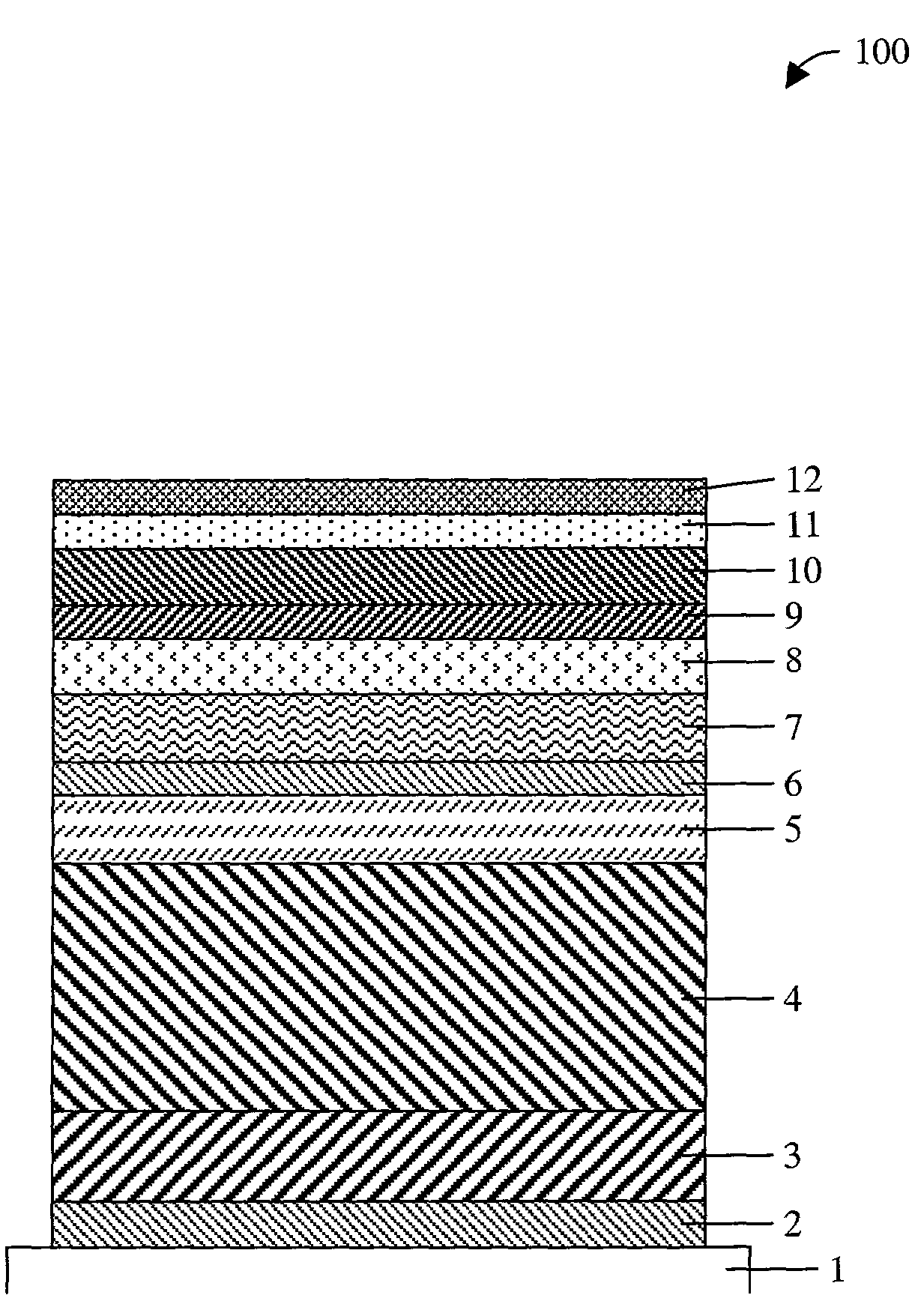
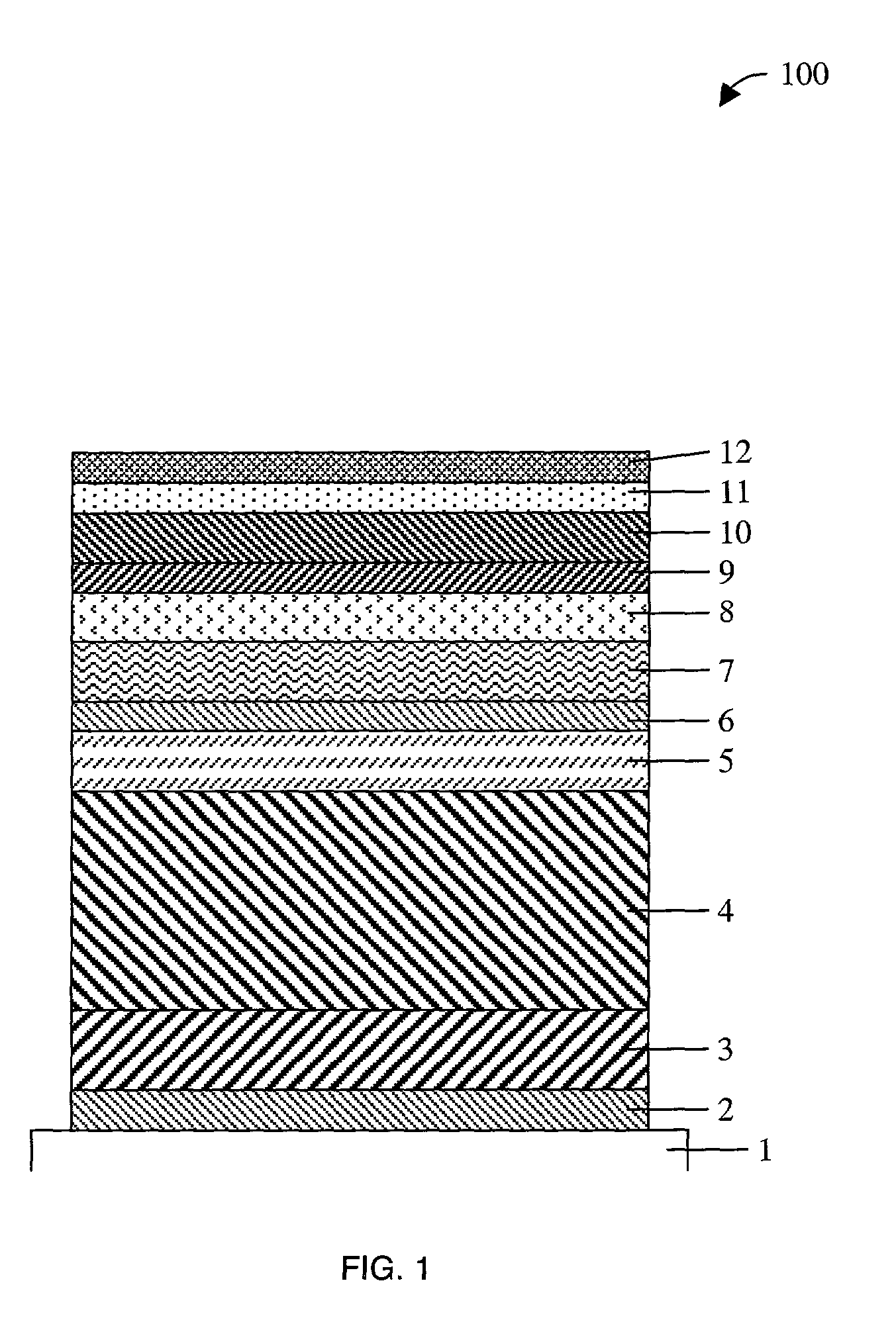

Image

  • Spin-valve type magnetoresistance sensor and thin-film magnetic head
  • Spin-valve type magnetoresistance sensor and thin-film magnetic head
  • Spin-valve type magnetoresistance sensor and thin-film magnetic head

Examples


Embodiment Construction

[0024]A method and apparatus for a magnetoresistance sensor are described. For purposes of discussing and illustrating the invention, several examples will be given in the context of a thin-film magnetic head. However, one skilled in the art will recognize and appreciate that the sensor may be used for sensing magnetic flux for other uses, for example, to sense voids in structures by inducing eddy currents in a material.

[0025]In the following description, for purposes of explanation, numerous specific details are set forth in order to provide a thorough understanding of the present invention. It will be evident, however, to one skilled in the art that the present invention may be practiced without these specific details. In some instances, well-known structures and devices are shown in block diagram form, rather than in detail, in order to avoid obscuring the present invention. These embodiments are described in sufficient detail to enable those skilled in the art to practice the in...


PUM

PropertyMeasurementUnit
thicknessaaaaaaaaaa
thicknessaaaaaaaaaa
thicknessaaaaaaaaaa

Abstract

A method and apparatus of a spin-type magnetoresistance sensor having a free and pinned magnetic layer stacked with a non-magnetic interposed layer are disclosed. Specifically, the spin-valve type magnetoresistance sensor of the present invention is equipped with a free ferromagnetic layer, a pinned ferromagnetic layer, a non-magnetic spacer layer which is sandwiched between the aforementioned ferromagnetic layers, an anti-ferromagnetic layer which is disposed adjacent to the aforementioned pinned ferromagnetic layer and which is used to pin the direction of magnetization of said pinned ferromagnetic layer, a non-magnetic back layer which is disposed adjacent to the aforementioned free ferromagnetic layer and which is stacked on the opposite side the free ferromagnetic layer from the aforementioned nonmagnetic spacer layer, and an electron-reflective layer which is disposed adjacent to the aforementioned back layer and which is stacked on the opposite side of the back layer from the aforementioned free ferromagnetic layer.

Description

[0001]This application claims the benefit of the filing date of the Japanese Application No.: 2000-109442 dated Apr. 11, 2000: “SPIN-VALVE TYPE MAGNETORESISTANCE SENSOR AND THIN-FILM MAGNETIC HEAD”. This application is also related to copending application Ser. No. 09 / 670,309 filed Sep. 26, 2000.FIELD OF THE INVENTION[0002]The present invention pertains to the field of magnetic recording. More particularly, the present invention relates to a thin-film head with a spin-valve type magnetoresistance sensor.BACKGROUND OF THE INVENTION[0003]The demand for magnetic disk storage capability continues to increase. This has resulted in increased storage density on disks. Increased storage density generally results in a decreased signal level from, for example, a reading head. Therefore, a magnetic head which has increased output may be beneficial.[0004]In the past, magnetic resistance sensors with a spin-valve film structure that have shown a large magnetic resistance effect (spin-valve MR se...

Claims


Application Information

Patent Timeline
Patent Type & Authority Patents(United States)
IPC IPC(8): G11B5/33G11B5/127G01R33/09G11B5/39H01L43/08
CPCB82Y10/00B82Y25/00G01R33/093G11B5/3903Y10T428/1107G11B2005/3996Y10T428/1171Y10T428/1129
Inventor UENO, MASAKINISHIDA, HIROSHIHIKAMI, FUMINORI
Owner WESTERN DIGITAL TECH INC
Why Eureka
Try Eureka