Methods and compositions for sealing oil containing subterranean zones

a technology of subterranean zone and composition, which is applied in the direction of lubricant composition, fluid removal, borehole/well accessories, etc., can solve the problems of formation fluid cross-flow and/or underground blowout, and the composition has often been unsuccessful, so as to delay the addition of viscosity and increase the viscosity

Active Publication Date: 2006-04-11
HALLIBURTON ENERGY SERVICES INC
View PDF10 Cites 45 Cited by
  • Summary
  • Abstract
  • Description
  • Claims
  • Application Information

AI Technical Summary

Benefits of technology

[0011]The sealing composition can also include an oil swellable elastomer therein for providing delayed additional viscosity.
[0012]A sulfur cross-linking agent can also be added to the composition to cross-link the elastomer and increase the viscosity further.

Problems solved by technology

During such drilling, subterranean vugs, fractures and other thief zones are often encountered whereby the drilling fluid circulation is lost and drilling operations must be terminated while remedial steps are taken.
Also, when a subterranean zone is penetrated containing fluids under pressure which exceeds the hydrostatic pressure exerted on the zone by the drilling fluid, formation fluid cross-flows and / or underground blowouts can and often do occur.
However, such compositions have often been unsuccessful due to delayed and inadequate viscosity development by the compositions.
The same type of problem often occurs when cross-linked hydrated gels and other similar plugging compositions are utilized.
A problem sometimes encountered in the use of the above described sealing composition is that the mixture can solidify prematurely prior to contacting oil-based fluids in the subterranean zone to be sealed.
Additionally, the aqueous rubber latex and the latex stabilizing surfactants utilized in the sealing composition are costly and make the use of the sealing composition expensive.

Method used


Image

  • Methods and compositions for sealing oil containing subterranean zones
  • Methods and compositions for sealing oil containing subterranean zones
  • Methods and compositions for sealing oil containing subterranean zones

Examples


example 1

[0031]A Hassler Sleeve setup typically used for fluid flow through cores was chosen for the purpose of this example. A 4.2″ long Berea core was fractured along the length of the core and dried in an oven overnight. Small strips of metal spacers of 1 mm thick were placed at points along the two sides of the core. The gaps between the spacer strips were filled with a mixture of sand and epoxy resin, and the outside surface of the assembled core was coated with epoxy glue. The epoxy glue was allowed to cure for at least 6 hrs.

[0032]The core was placed in the Hassler rubber sleeve. An overburden pressure, generally 300–500 psi higher than the mud pressure, was exerted on the rubber sleeve. A back pressure of 110 psi was applied on the core. The bottom end of the core was connected to a reservoir containing the base oil. Initially, the core assembly was connected to a separate vessel which was quickly charged with a freshly prepared mixture of a sealing composition of this invention and ...

example 2

[0036]To a sample of 100 ml of the oil-based drilling fluid used in Example 1, about 20 grams of a styrene-butadiene block polymer supplied by Atofina Elastomers, Inc. of Houston, Tex. under the trade name FINAPRENE™ which had been ground to a particle size of approximately 200–400 microns was added and allowed to stand at room temperature. In about 3 hrs, the entire fluid mass became a rubbery, non-flowing mass. When the drilling fluid was replaced by either the base fluid used in the drilling fluid or kerosene, a similar result was obtained.


PUM

PropertyMeasurementUnit
weight %aaaaaaaaaa
thickaaaaaaaaaa
pressureaaaaaaaaaa

Abstract

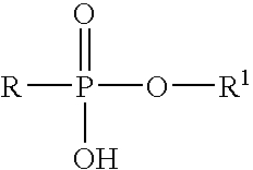
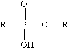
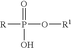
The present invention provides methods and compositions for sealing subterranean zones containing oil to prevent the uncontrolled flow of fluids into or from the zones. The compositions basically comprise water, a phosphonic acid ester, a multivalent metal ion releasing compound and an organophilic clay.

Description

BACKGROUND OF THE INVENTION[0001]1. Field of the Invention[0002]The present invention relates to improved methods and compositions for sealing oil containing subterranean zones penetrated by well bores.[0003]2. Description of the Prior Art[0004]In the drilling of oil and gas wells using the rotary drilling method, drilling fluid is circulated through the drill string and drill bit and then back to the surface by way of the well bore being drilled. The drilling fluid maintains hydrostatic pressure on the subterranean zones through which the well bore is drilled and circulates cuttings out of the well bore. During such drilling, subterranean vugs, fractures and other thief zones are often encountered whereby the drilling fluid circulation is lost and drilling operations must be terminated while remedial steps are taken. Also, when a subterranean zone is penetrated containing fluids under pressure which exceeds the hydrostatic pressure exerted on the zone by the drilling fluid, formati...

Claims


Application Information

Patent Timeline
Patent Type & Authority Patents(United States)
IPC IPC(8): C09K8/528E21B33/138E21B43/00
CPCC09K8/5045C10M1/08C09K8/5083C09K8/506
Inventor REDDY, B. RAGHAVAFUNKHOUSER, GARY P.BROWN, DAVID L.
Owner HALLIBURTON ENERGY SERVICES INC
Why Eureka
Try Eureka