Tuning of nuclear magnetic resonance logging tools

a nuclear magnetic resonance and logging tool technology, applied in the field of nuclear magnetic resonance logging tool tuning, can solve the problems of inability to perform lfst during nmr measurement, time-consuming, and not always practical, and achieve the effect of reducing the need for conventional off-line time-consuming tuning procedures, reducing systematic errors in porosity determination, and optimizing the signal to noise ratio

Active Publication Date: 2006-04-11
SCHLUMBERGER TECH CORP
View PDF14 Cites 22 Cited by
  • Summary
  • Abstract
  • Description
  • Claims
  • Application Information

AI Technical Summary

Benefits of technology

[0012]In accordance with the present invention, the echo signal is analyzed to detect any mistuning of the rf frequency from the Larmor frequency. Likewise, either an independent measurement or the echo signal phase is used to monitor the detuning of the rf frequency with respect to the resonance frequency of the antenna. For the purposes of the present invention, the term “antenna” is the system component that transmits the rf magnetic field and detects the magnetic field due to the NMR precession, such as an NMR coil. The tuning of the antenna and the tuning of the rf frequency with respect to the Larmor frequency may be adjusted, if necessary. This “retuning” can be done continuously while logging to account for any local changes in the static magnetic field, allowing proper tuning of the tool to be maintained while logging and reducing the need for conventional off-line time-consuming tuning procedures. The resulting improvements are a reduction of systematic errors in porosity determination and the optimization of the signal to noise ratio.
[0013]The tuning procedure of the present invention is based on information obtained from the NMR signal and may be implemented using the presently used pulse sequences, in particular sequences based on the CPMG sequence. Therefore, the tuning is measured as seen by the spins without requiring a change in the pulse sequence or the introduction of additional signals into the antenna.
[0019]The antenna tuning process may be automated by measuring the amplitudes of calibration signals generated at more than one frequency. These amplitudes may be analyzed to determine mistuning of the antenna relative to the operating frequency. In one embodiment, a maximum amplitude may be identified to determine antenna mistuning. The system tuning may be maintained by repeating (a) through (d) while operating the tool and implementing a feedback loop. Further, the effects of the antenna mistuning may be minimized by performing (c) and (d) nearly simultaneously.

Problems solved by technology

This is time consuming and may require that the tool be stationary in the well.
The LFST cannot be performed during a NMR measurement and, therefore, needs to be performed beforehand.
This is not always practical.
However, in many logging environments, station stops are not possible.
Further, in fluid sampling tools, the flowing fluid will not likely have a constant hydrogen index.
During a continuous log it is not possible to verify directly that the operating frequency is tracking any changes in the Larmor frequency.
However, a sudden change in the magnetic field caused by magnetic particles attracted and deposited on the magnets can cause unknown shifts in the Larmor frequency that invalidate the tool calibration.
But this determination is coarse and does not allow for quantitative correction of the shifts.

Method used


Image

  • Tuning of nuclear magnetic resonance logging tools
  • Tuning of nuclear magnetic resonance logging tools
  • Tuning of nuclear magnetic resonance logging tools

Examples


Embodiment Construction

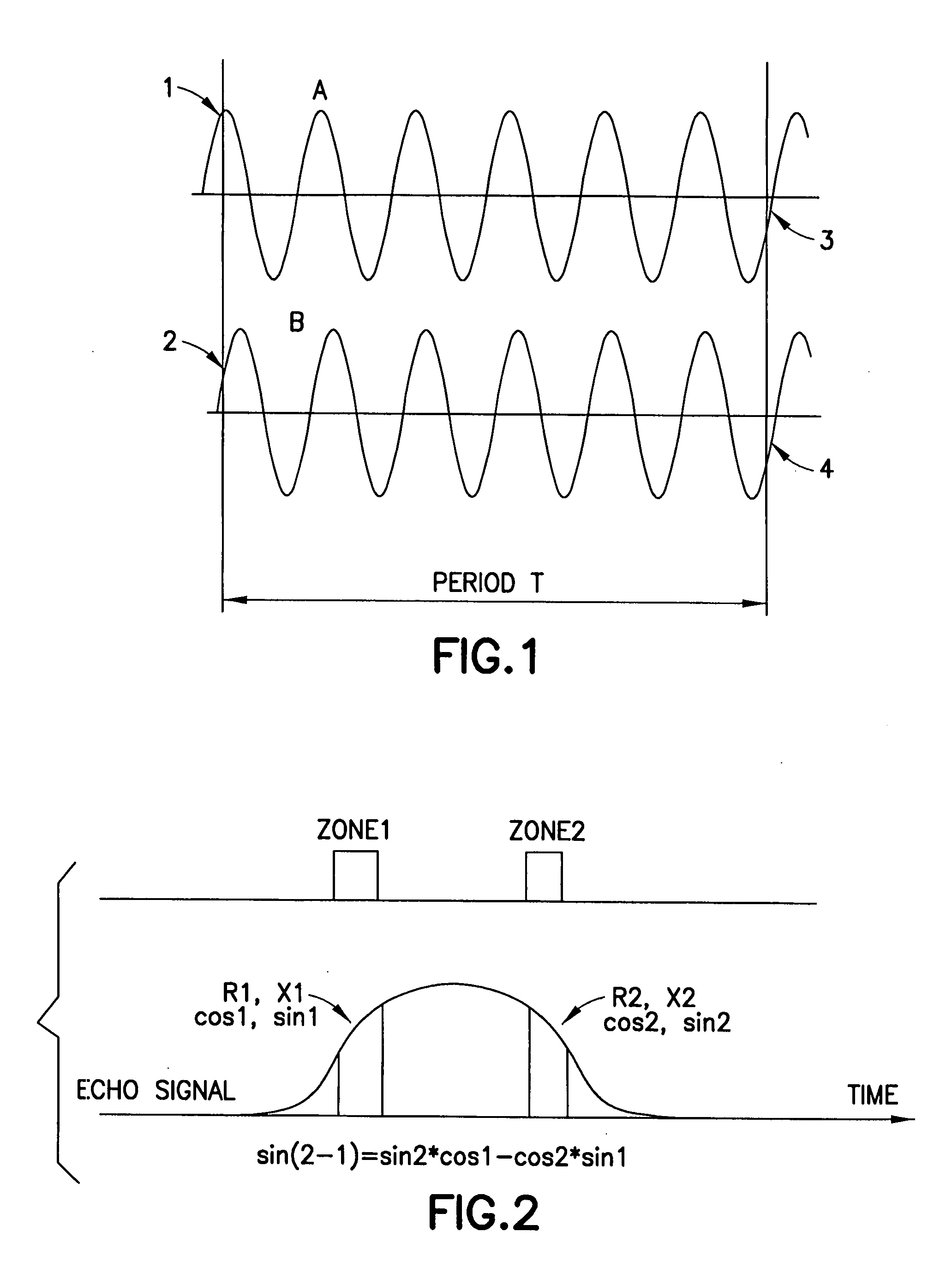
[0040]In an embodiment of the present invention, mistuning of the rf frequency from the Larmor frequency is measured wherein the main frequency component of the echo signal (Larmor Frequency) is compared with the rf frequency (frequency of the rf signals transmitted by the instrument and the reference of the phase-sensitive echo demodulation) by two or more phase measurements of the echo signal at fixed time intervals along the echo. This principle is illustrated in FIG. 1, which shows two phase measurements, phase1 and phase2, separated by a period T, resulting in the measurement of detuning as proportional to (phase2−phase1) / T. More particularly, FIG. 1 shows an echo signal (A) and a detector reference (calibration signal) at rf frequency (B). Measured phase1 is the difference between phases of the echo signal at 1 [ph1(1f)] and the detector reference at 2 [ph1(r)]. Accordingly, phase1=ph1(1f)−ph1(r). Measured phase2 is the difference between phases of echo signal at 3 [ph1(1f)+wl...


PUM


Abstract

A method for tuning a nuclear magnetic resonance (NMR) tool having an operating frequency and equipped with an antenna, is disclosed comprising: (a) transmitting a rf magnetic field to a sample under investigation; (b) receiving an NMR signal from the sample within a detection window; (c) determining mistuning of said antenna relative to said operating frequency; (d) analyzing the received echo signal to determine mistuning of the received signal from the operating frequency. The mistuning of the received signals from the operating frequency may be determined by analyzing any changes in phase of the echo along the echo signal. The antenna tuning process may be automated by measuring calibrated signal amplitudes at more than one frequency and identifying a maximum amplitude. The system tuning may be maintained by repeating (a) through-(d) while operating the tool and implementing a feedback loop.

Description

BACKGROUND OF THE INVENTION[0001]Pulsed nuclear magnetic resonance (NMR) measurements use bursts of electromagnetic fields (also called rf pulses) at a specific frequency (also called the operating frequency or rf frequency) to induce response echoes in the material under measurement. To obtain the maximum response to a particular element, the operating frequency should be at the “Larmor frequency” (also called the “sweet spot” of the instrument). The Larmor frequency is dependent upon local static magnetic fields, which may change during logging. For example, temperature changes or the accumulation of magnetic debris on the tool will affect the strength of the static magnetic field and influence logging measurements. Because the tool is calibrated relative to the Larmor frequency, changes in the static magnetic field must be accounted for, such as by changing the operating frequency of the pulses and the resonance frequency of the antenna.[0002]Accordingly, two frequencies should b...

Claims


Application Information

Patent Timeline
Patent Type & Authority Patents(United States)
IPC IPC(8): G01V3/00G01R33/36G01R33/44
CPCG01R33/3628G01N24/081
Inventor BORDON, ERNESTOHURLIMANN, MARTIN D.MINH, CHANH CAO
Owner SCHLUMBERGER TECH CORP
Why Eureka
Try Eureka