Parallel MR imaging with use of multi-coil made of plural element coils

a multi-coil, coil technology, applied in the field of magnetic resonance imaging, can solve the problems of increasing manufacturing costs, not being able to continue to use calibration data once acquired over a plurality of patients, and fold-around phenomena at edges

Inactive Publication Date: 2006-04-11
TOSHIBA MEDICAL SYST CORP
View PDF19 Cites 63 Cited by
  • Summary
  • Abstract
  • Description
  • Claims
  • Application Information

AI Technical Summary

Benefits of technology

[0018]The present invention has been made to overcome the foregoing various problems, and a main object of the present invention is to provide both of an MR signal reception apparatus th...

Problems solved by technology

There are, however, caused folding phenomena (or called wrap-around) at edges of each image.
Continuing to use calibration data once acquired over a plurality of patients is not so welcomed because of such reasons.
However, since it is generally true that increasing the number Nch of channels will lead to a rise in the manufacturing cost of the MRI system, the number Nch of channels is limited in the practical MRI systems.
Without such proper arrangement, the image quality may be deteriorated due to a decreased SNR or artifacts, or ...

Method used


Image

  • Parallel MR imaging with use of multi-coil made of plural element coils
  • Parallel MR imaging with use of multi-coil made of plural element coils
  • Parallel MR imaging with use of multi-coil made of plural element coils

Examples


first embodiment

[0064](First Embodiment)

[0065]With reference to FIGS. 1 to 7, a first embodiment of the MR signal reception apparatus and the magnetic resonance imaging system of the present invention will now be described.

[0066]In this embodiment, the magnetic resonance imaging system will perform parallel MR imaging, wherein the MR signal reception apparatus is functionally included in the magnetic resonance imaging system.

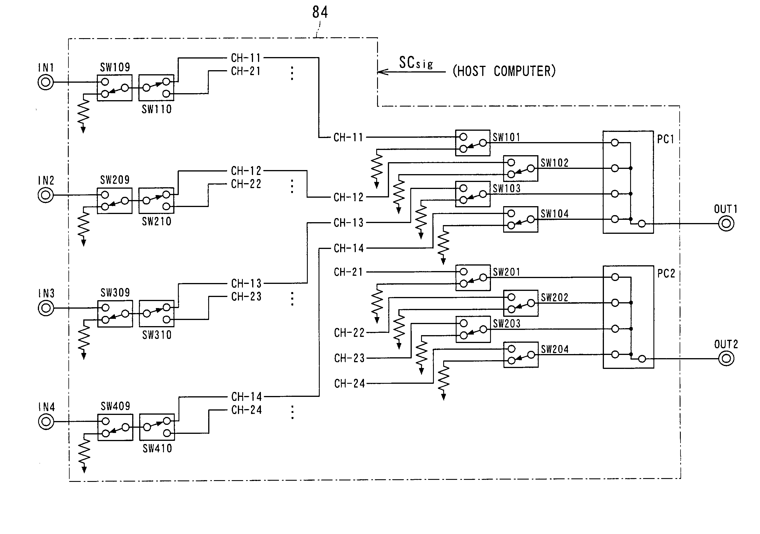
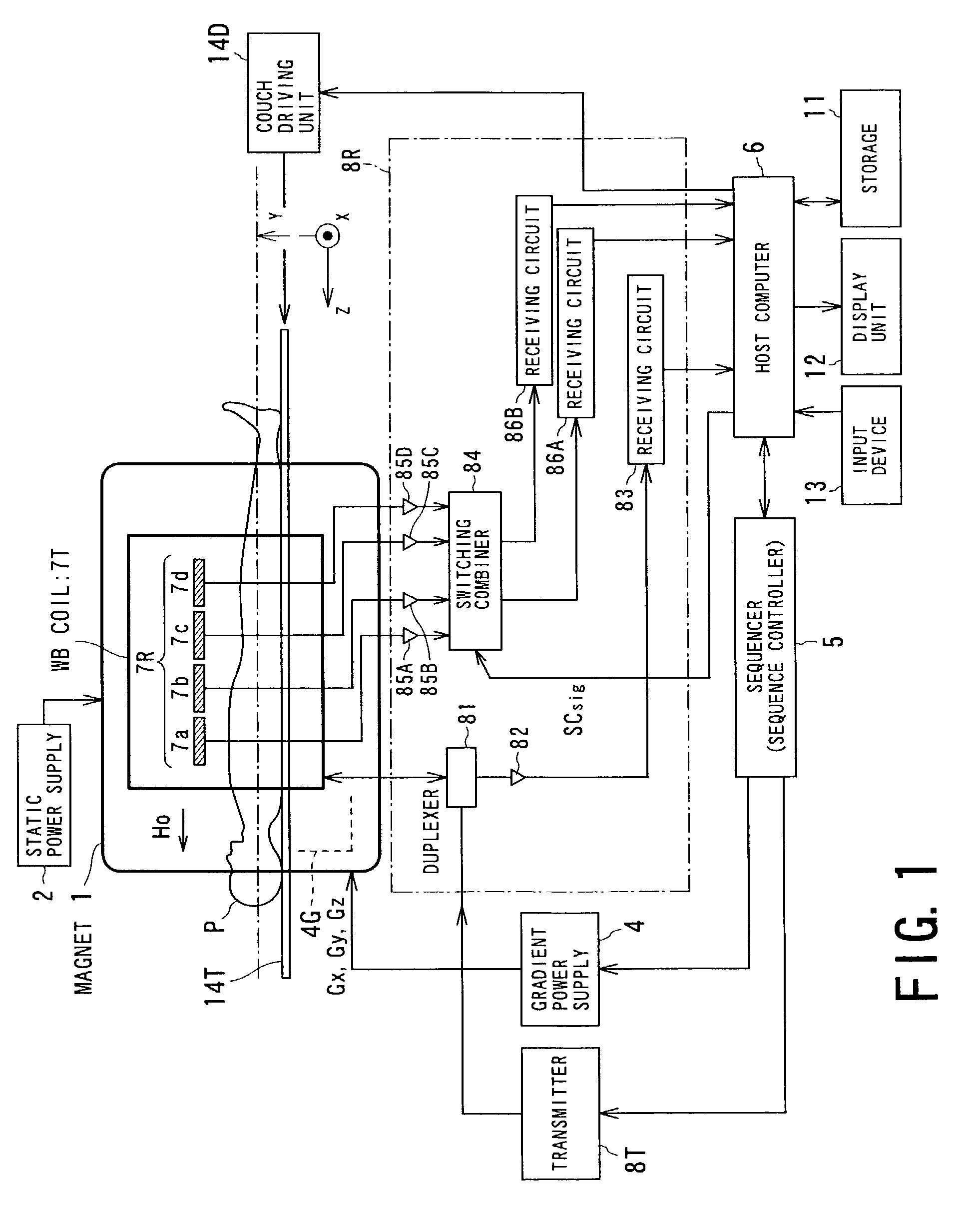
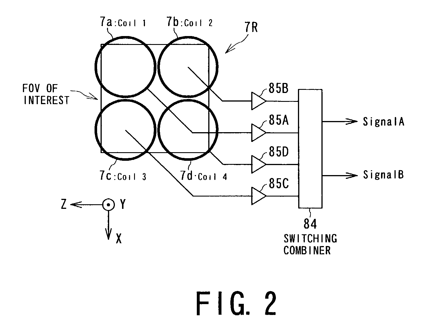
[0067]With reference to FIG. 1, the entire configuration of the magnetic resonance imaging system according to the present embodiment will now be outlined.

[0068]This imaging system is configured to perform parallel MR imaging with the use of a multi-coil for MR images. As shown in FIG. 1, the system comprises a patient couch on which a patient P as an object to be imaged lies down, static-field generating part for generating a static magnetic field, magnetic-gradient generating part for appending positional information to the static magnetic field, transmitting / receiving part f...

second embodiment

[0173](Second Embodiment)

[0174]Referring to FIGS. 13A to 13C, to 16, various configurations of switching and combining signals detected from various types of multi-coils adopted for performing the parallel MR imaging according to the first embodiment. These configurations are used to switch and combine signals based on the size of an FOV (field of view) given as one imaging condition.

[0175]FIGS. 13A to 13C show the arrangement of a multi-coil 20 of which number of channels are larger than four channels described in the first embodiment. In this example, as shown in FIG. 13C, the multi-coil 20 is made up of twenty-four RF coils (i.e., twenty-four channels) arranged around a region to be imaged (including a region of interest) of an object P. The RF coils consist of object's right-side coils R1 to R4, object anterior-right coils AR1 to AR4, object's anterior-left coils AL1 to AL4, object's left-side coils L1 to L4, object's posterior-left coils PL1 to PL4, and object's posterior-right...

third embodiment

[0186](Third Embodiment)

[0187]Referring to FIGS. 17 to 21, a third embodiment of the MR signal reception apparatus according to the present invention will now be described. In this embodiment, the same or identical constituents as or to those descried in the foregoing first embodiment will be described with use of the same reference, omitting or simplifying the explanation.

[0188]The third embodiment essentially relates to an MR signal reception apparatus having a reception multi-coil including a plurality of element coils and switching means for switching a reception state of MR signals detected by the element coils depending on imaging conditions. The switching means is formed into means for selectively switching the plurality of element coils into a desired one mode from a plurality of combined coil modes predetermined in compliance with the imaging conditions.

[0189]FIG. 17 outlines the configuration of the MR signal reception apparatus according to the present embodiment. This MR...


PUM


Abstract

A magnetic resonance imaging system includes an MR signal reception apparatus comprising a receiving multi-coil and a switchover member. The receiving multi-coil receives MR signals and is composed of a plurality of element coils. The switchover member is configured to switch reception states of the MR signals received by the plurality of element coils in response to imaging conditions. The switchover member connects output paths of the MR signals from the plurality of element coils to a receiver, to reception channels in the receiver in response to the imaging conditions. The reception channels is less in number than the element coils. The imaging conditions are for example directed to parallel MR imaging.

Description

BACKGROUND OF THE INVENTION[0001]The present invention relates to magnetic resonance imaging for obtaining MR (magnetic resonance) images of an object based on the magnetic resonance phenomenon of spins of the object, and in particular to a switchover technique of signals or coils when MR signals received by an RF coil are given a signal processing apparatus for reception.[0002]A particularly preferred example of the present invention is a switchover technique of signals or coils when MR signals received by a plurality of element coils composing a multi-coil serving as a receiving RF coil are given a signal processing apparatus for reception. Such a multi-coil is called a phased array coil (PAC). Another preferred example is to apply the above switchover technique to fast MR imaging that uses the foregoing multi-coil to conduct imaging at higher speed (hereafter, such imaging is called parallel MR imaging).[0003](Related Art)[0004]Magnetic resonance imaging can be summarized as an i...

Claims


Application Information

Patent Timeline
IPC IPC(8): G01V3/00A61B5/055G01R33/3415G01R33/36G01R33/561
CPCG01R33/3415G01R33/3664G01R33/5611
Inventor MACHIDA, YOSHIOHAMAMURA, YOSHINORIKASSAI, YOSHIMORIOKAMOTO, KAZUYASOMA, KAZUHIRO
Owner TOSHIBA MEDICAL SYST CORP
Why Eureka
Try Eureka