Programmable current booster for faster edge-rate output in high speed applications

a technology of programmable current and output signal, which is applied in the direction of logic circuit coupling/interface arrangement, pulse technique, instruments, etc., can solve the problems of increasing output voltage swing and becoming increasingly difficult to meet both requirements, and achieves the effect of maximum flexibility and fast rising and falling edge rates

Inactive Publication Date: 2006-04-11
ALTERA CORP
View PDF9 Cites 19 Cited by
  • Summary
  • Abstract
  • Description
  • Claims
  • Application Information

AI Technical Summary

Benefits of technology

[0008]Embodiments of the present invention allow for bifurcated control of the switching rate and the holding state of a given output signal, in order to achieve faster rising and falling edge rates without the undesirable increased output voltage swing. Fast edge rates require a large switching current to charge up the capacitive loading, while providing a small holding current to limit the output voltage swing. The programmable current booster described here provides a separate switching current during the output switching phase, while not affecting the holding current or the output voltage swing. Importantly, the strength and the duration of the switching booster current are programmable to allow a user the maximum flexibility in conforming to any of the I / O signaling standards such as HSTL, SSTL, LVDS, LVPECL or HyperTransport, though the present invention is not limited to only those standards. Embodiments of the present invention may be equally applicable to other relevant existing standards as well as those standards which have yet to be proposed or fully developed.

Problems solved by technology

Overdriving for a faster edge rate directly results in increased output voltage swing.
It is therefore becoming increasingly difficult to meet both requirements when the same output current settings are used for both switching and holding states as circuit speeds continue to increase.

Method used


Image

  • Programmable current booster for faster edge-rate output in high speed applications
  • Programmable current booster for faster edge-rate output in high speed applications
  • Programmable current booster for faster edge-rate output in high speed applications

Examples


embodiment

Differential Embodiment

[0034]The programmable current booster according to the embodiment of the present invention described above for a single-ended output driver may also be applied in a differential output driver. Differential drivers are used to implement differential signals which are carried on pairs of conductors in which the signals propagate in parallel. Differential signals are opposite in polarity and referenced relative to each other, rather than to ground.

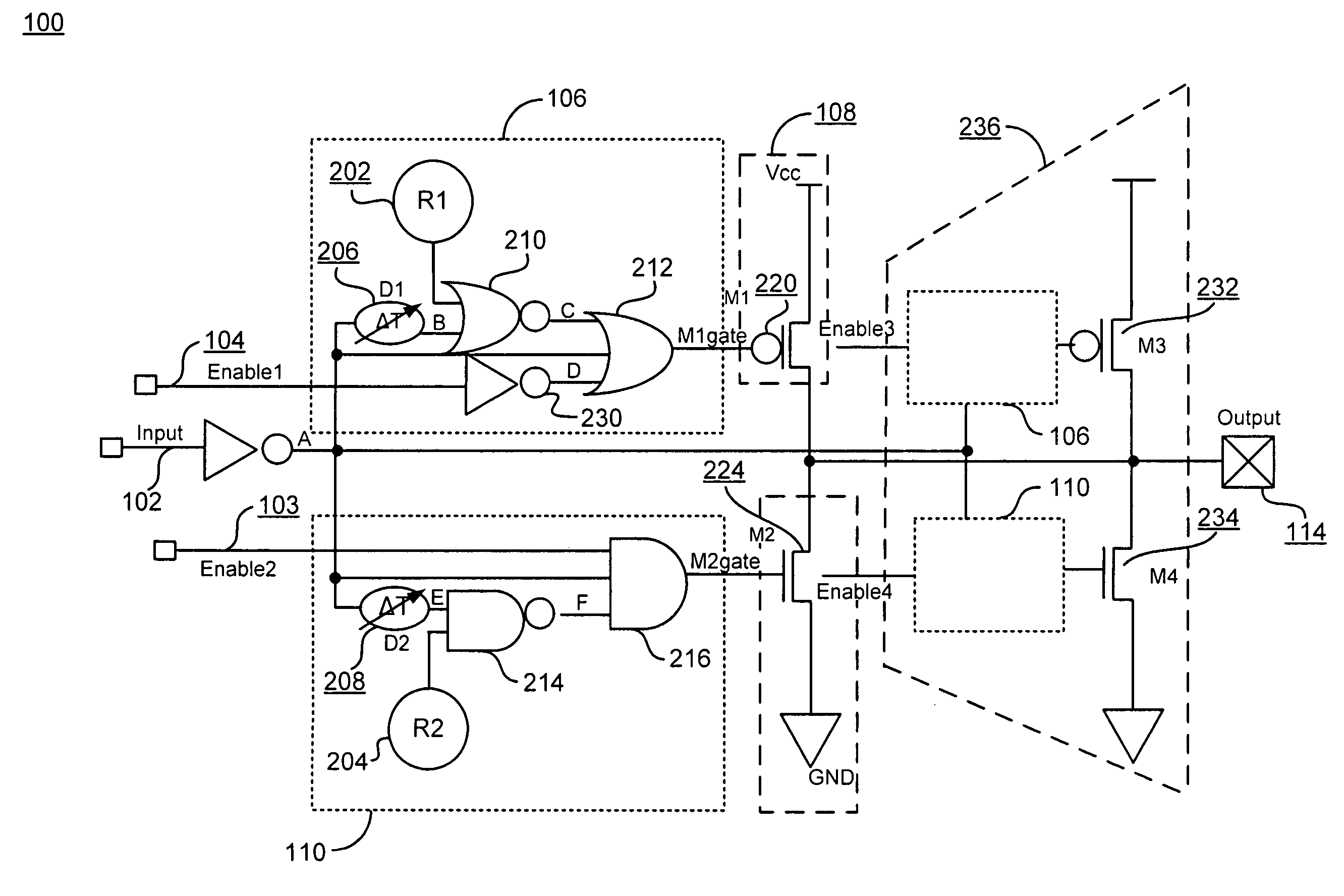
[0035]FIG. 3 is a preferred implementation of a differential output driver 700 according to one embodiment of the present invention. Output transistors 516, 518, 528 and 530 provide holding output current, while output transistors 522, 523, 520 and 521 are switching current boosters. holding stage rising edge control circuits 510 have the analogous delay as the switching booster control circuits 106, so the holding and switching currents are switched on simultaneously. The control circuits 106 for current-regulating ou...


PUM


Abstract

An AC current booster for high speed, high frequency applications having a single-ended output embodiment and a differential output embodiment. The embodiments of the present invention allow bifurcated control of the AC switching rate and the DC state of a given output signal, in order to achieve faster rising and falling edge rates without an undesirable increase in output voltage swing.

Description

FIELD OF THE INVENTION[0001]Embodiments of the present invention relate to achieving faster output signal edge rates in high frequency signaling for programmable logic devices (PLDs) and other integrated circuits (ICs), most particularly to signals which may be designed to conform to any one of several different high frequency input / output (I / O) signaling standards.BACKGROUND OF THE INVENTION[0002]Programmable logic devices (PLDs) are well known. Commonly, a PLD has a plurality of substantially identical logic elements, each of which can be programmed to perform certain desired logic functions. The logic elements have access to a programmable interconnect structure that allows a user to interconnect the various logic elements in almost any desired configuration. The interconnect structure also provides access to a plurality of I / O pins, with the connections of the pins to the interconnect structure also being programmable and being made through suitable I / O buffer or driver circuitr...

Claims


Application Information

Patent Timeline
Patent Type & Authority Patents(United States)
IPC IPC(8): H03K3/00G05F1/10H03K19/00H03K19/017H03K19/0185
CPCH03K19/0016H03K19/018507H03K19/01721H03K19/01707
Inventor WANG, BONNIE I.SUNG, CHIAKANGNGUYEN, KHAI Q.WANG, XIAOBAO
Owner ALTERA CORP
Why Eureka
Try Eureka