

Primary radiator for parabolic antenna
- Summary
- Abstract
- Description
- Claims
- Application Information
AI Technical Summary
Benefits of technology
Problems solved by technology
Method used
Image

Examples
first embodiment
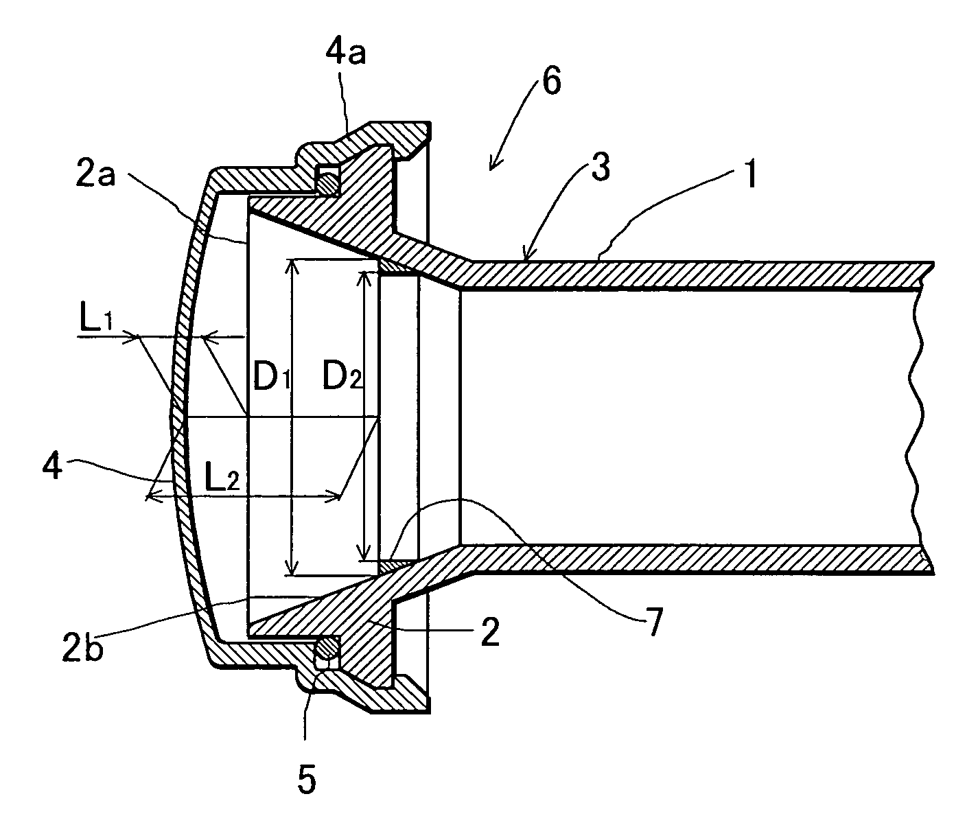
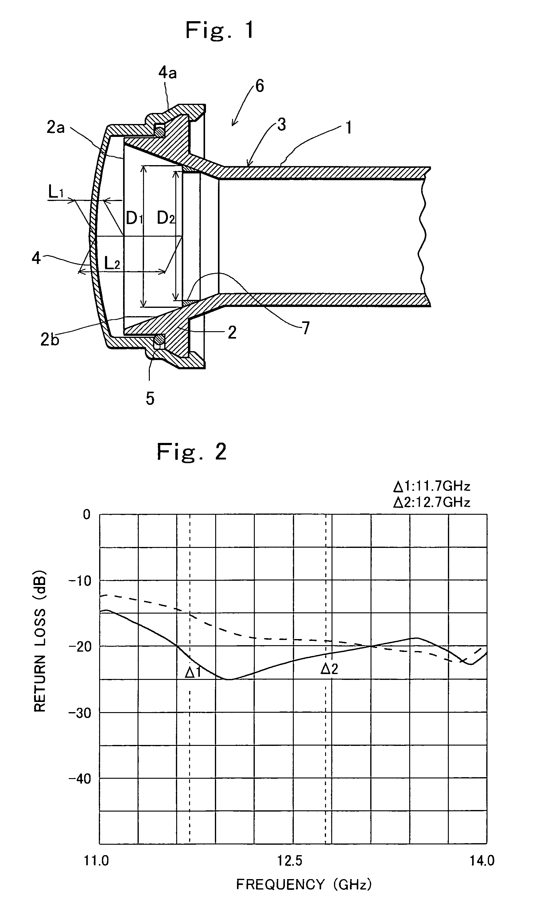
[0028]FIG. 1 shows the invention. In FIG. 1, a reference numeral 1 denotes a circular waveguide, and a reference numeral 2 denotes a horn part provided at one end of the waveguide 1. In this embodiment, the waveguide 1 and the horn part 2 are made of aluminum. The horn part 2 is integrally formed at one end of the waveguide 1, and an inner surface of the horn part 2 is a conical tapered surface 2b having a cross section gradually increasing toward an open end 2a thereof. The waveguide 1 and the horn part 2 constitute a radiator body 3 having an inner surface rotationally symmetric with respect to a central axis. The radiator body is made by die casting.
[0029]A reference numeral 4 denotes a waterproof cover covering the open end 2a of the horn part 2 for preventing rainwater from entering the radiator body 3. The waterproof cover 4 is made of ABS resin or polypropylene resin so as to have a uniform thickness. The thickness of the waterproof cover 4 is set to be sufficiently shorter t...
second embodiment
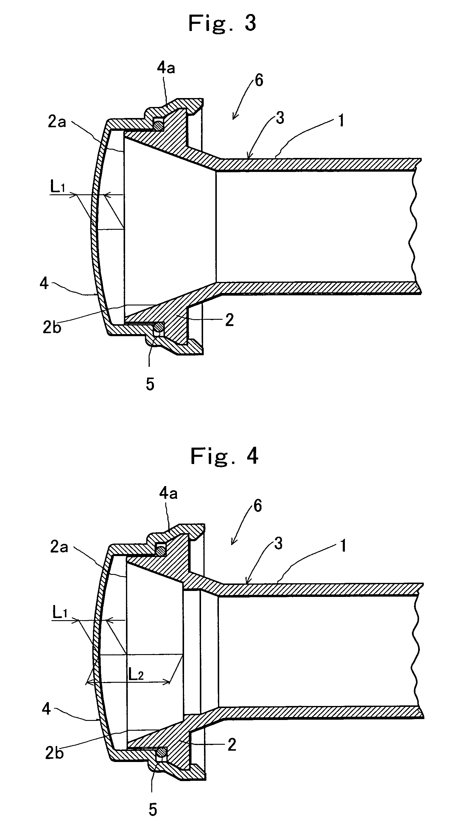
[0050]FIG. 4 is a vertical sectional view of a primary radiator for a parabolic antenna according to the invention. In this embodiment, when a radiator body 3 constituted by a waveguide 1 and a horn part 2 is made, a step 7 is integrally formed on an inner surface of the horn part 2. Materials, shapes, positions, sizes or the like of the waveguide 1 and the horn part 2 are the same as in the embodiment in FIG. 1.
[0051]When the step 7 is integrally provided on the inner surface of the horn part 2, the step 7 can be formed simply by forming a die part for the step 7 in part of a die used for die casting the radiator body, thus simplifying manufacture of the radiator body having the step.
third embodiment
[0052]FIG. 5 is a vertical sectional view of a primary radiator for a parabolic antenna according to the invention. In this embodiment, a step 7 is integrally provided with a waveguide 1 in a border between the waveguide 1 and a horn part 2 of a radiator body 3. Other points are the same as in the embodiment in FIG. 1.
[0053]When the step 7 is thus provided in position, a distance L1 between an inner surface of a waterproof cover 4 and an open end 2a of the horn part 2 is adjusted so as to adjust a distance between the inner surface of the waterproof cover 4 and the step 7 to be substantially equal to an odd multiple of 180° in terms of a phase angle of a radio wave propagating in the radiator body, and a size of the step 7 is appropriately adjusted so as to allow radio waves reflected on the waterproof cover to be cancelled out by radio waves reflected on the step 7. Even in such a configuration, reflection loss can be reduced without a long distance L1 between the inner surface of ...
PUM
 Abstract
Description
Claims
Application Information