Image-forming optical system

a technology of optical system and image, applied in the field of image-forming optical system, can solve the problems of difficult to realize compactness of optical system, sensitivity of image pickup device, etc., and achieve the effect of high optical performance, effective correction of image pickup device sensitivity, and convenient realization of compactness

Active Publication Date: 2006-04-11
COMPACT LENS TECH LLC
View PDF7 Cites 8 Cited by
  • Summary
  • Abstract
  • Description
  • Claims
  • Application Information

AI Technical Summary

Benefits of technology

[0010]It is an advantage of the present invention to provide an image-forming optical system for cameras using an image pickup device that comprises a small number of lenses to easily realize compactness and satisfies a requirement for a high optical performance.
[0011]It is another advantage of the present invention to provide a miniature image-forming optical system that increases the peripheral light to effectively correct the sensitivity of the image pickup device.
[0012]In a first aspect of the present invention, there is provided an image-forming optical system comprising, in order from an object side: an iris diaphragm; a first lens hav

Problems solved by technology

The optical system of which the image pickup device is sensitive to the light in the infrared (IR) region may have a problem of “saturation,” so there is a need for additionally using an infrared (IR) cut-off filter to red

Method used


Image

  • Image-forming optical system
  • Image-forming optical system
  • Image-forming optical system

Examples


first embodiment

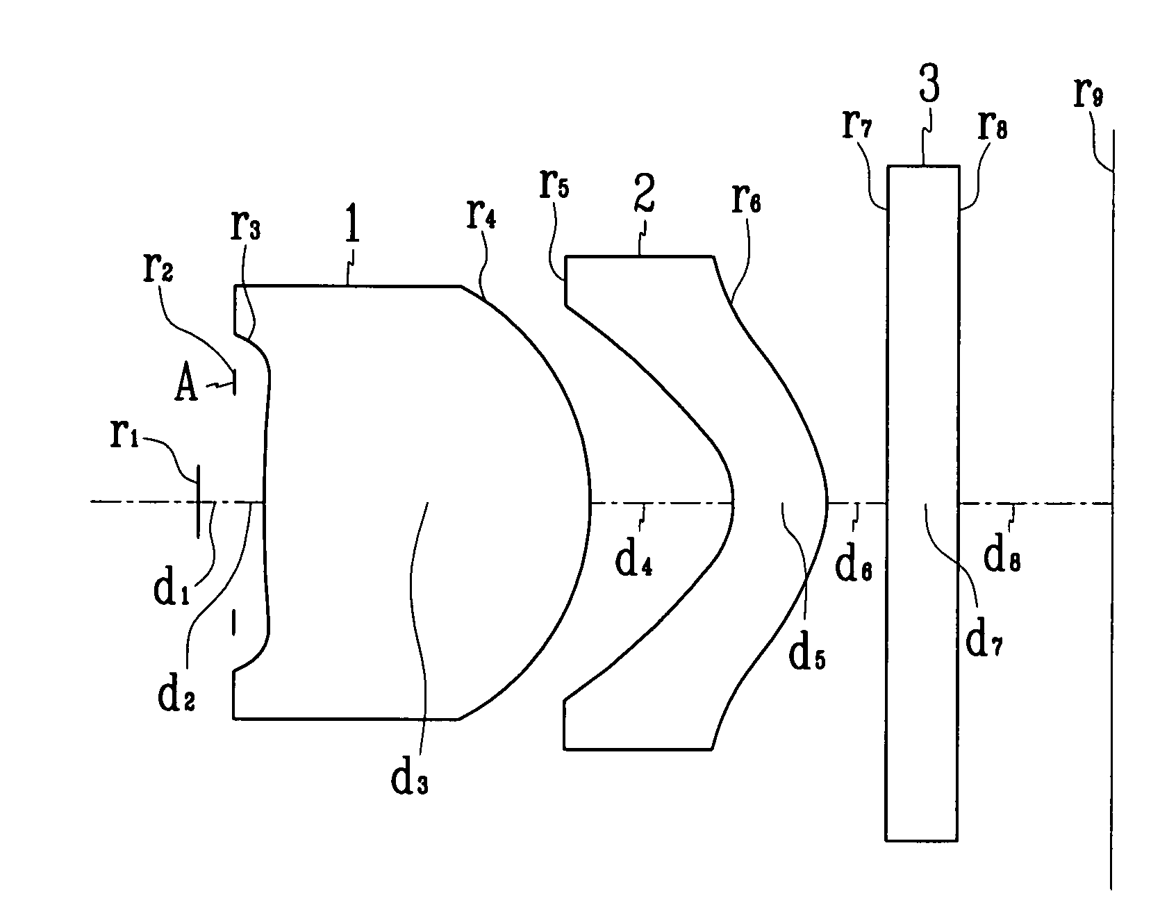
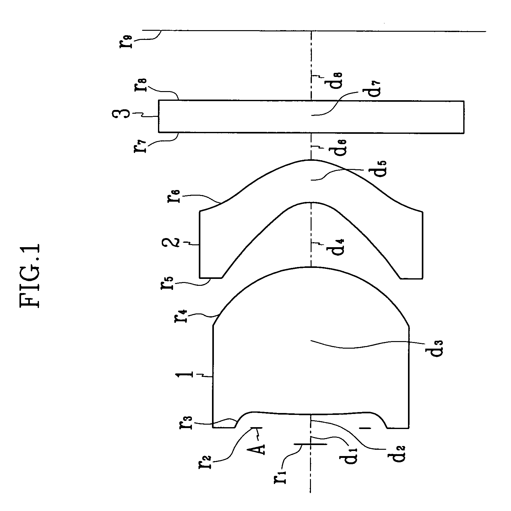
[0061]An F-number Fno of the image-forming optical system according to the present invention has a value of 2.84, a focal distance f is 2.445 mm, and an angle of view (2ω) is 33.42°.

[0062]FIG. 1 shows the configuration of an image-forming optical system according to a first embodiment of the present invention that has these characteristics, and Table 1 lists the embodied values for the component lenses of the image-forming optical system shown in FIG. 1.

[0063]

TABLE 1Radius ofThickness,RefractiveFace NumberCurvature (r)Distance (d)Index (nd)Variance (v) 1∞0.150000 2∞0.120000*32.867001.3600001.52556.2*4−0.881000.566055*5−0.369000.4000001.58431.0*6−0.610000.270354 7∞0.3000001.51764.2 8∞0.649646(image side) 9∞0.000000

[0064]The symbol “*” indicates the aspheric surface. Aspheric surface coefficients can be expressed by the following Equation:

[0065]x=cy21+1-(K+1)⁢c2⁢y2+Ay4+By6+Cy8+Dy10[Equation⁢⁢1]

where x is the distance along the optical axis from the vertex of the lens; y is the distanc...

second embodiment

[0069]For an image-forming optical system according to the present invention, the F-number Fno is 2.8, the focal length f is 3.284 mm, and the angle of view (2ω) is 34.57°.

[0070]FIG. 3 shows the configuration of the image-forming optical system according to the second embodiment of the present invention that has these characteristics, and Table 3 lists the embodied values associated with each component lens of the image-forming optical system shown in FIG. 3.

[0071]

TABLE 3Radius ofThickness,RefractiveFace NumberCurvature (r)Distance (d)Index (nd)Variance (v) 1∞0.150000 2∞0.050000*3−258.880001.0190001.52556.2*4−1.071000.509602*5−0.554000.4000001.60727.59*6−0.794000.785328 7∞0.5500001.51764.2 8∞1.597070(image side) 9∞0.000000

[0072]The symbol “*” indicates the aspheric surface. In the second embodiment, the first and second lenses 1 and 2 respectively have an aspheric surface on both sides thereof. The aspheric surface coefficients are presented in Table 4.

[0073]

TABLE 4Aspheric SurfaceA...

third embodiment

[0075]For an image-forming optical system according to the present invention, the F-number Fno is 2.8, the focal length f is 3.385 mm, and the angle of view (2ω) is 33.93°.

[0076]FIG. 5 shows the configuration of the image-forming optical system according to the third embodiment of the present invention that has the characteristics, and Table 5 lists the embodied values associated with each component lens of the image-forming optical system shown in FIG. 5.

[0077]

TABLE 5Radius ofThickness,RefractiveFace NumberCurvature (r)Distance (d)Index (nd)Variance (v) 1∞0.150000 2∞0.030000*36.513001.4500001.52556.2*4−1.259000.923303*5−0.705000.6900001.60727.59*6−1.138000.200014 7∞0.5500001.51764.2 8∞1.044995(image side) 9∞0.000000

[0078]The symbol “*” indicates the aspheric surface. In the third embodiment, the first and second lenses 1 and 2 respectively have an aspheric surface on both sides thereof. The aspheric surface coefficients are presented in Table 6.

[0079]

TABLE 6Aspheric SurfaceAspheric...


PUM


Abstract

The present invention is directed to an image-forming optical system. The image-forming optical system according to the present invention contains, in order from an object side: an iris diaphragm; a first lens having a positive refractive power and at least one aspheric surface; and a second lens having a negative refractive power and at least one aspheric surface. In accordance with the present invention, there is provided an image-forming optical system for cameras using an image pickup device that has a small number of lenses to easily realize the compactness and satisfies a requirement for a high optical performance.

Description

CROSS REFERENCE TO RELATED APPLICATION[0001]This application claims priority to and the benefit of Korean Patent Application No. 2003-40205 filed on Jun. 20, 2003 in the Korean Intellectual Property Office, the content of which is incorporated herein by reference.BACKGROUND OF THE INVENTION[0002](a) Field of the Invention[0003]The present invention relates to an image-forming optical system. More specifically, the present invention relates to a miniature image-forming optical system for cameras using an image pickup device such as a charge coupled device (CCD).[0004](b) Description of the Related Art[0005]Recently, the use of electronic still cameras and video cameras employing a CCD or a solid-state image pickup device has been expanding rapidly, and the needs for miniaturization and weight / cost savings are increasing. With the desire for greater compactness, miniature cameras such as mobile camera, web camera, or the like are increasingly used. Such miniaturization and weight / cost...

Claims


Application Information

Patent Timeline
IPC IPC(8): G02B3/02G02B15/16G02B9/04G02B13/00
CPCG02B13/003G02B9/04G02B3/04G02B13/18G02B9/10
Inventor KIM, JAE-BUMKIM, YOUNG-RAN
Owner COMPACT LENS TECH LLC
Why Eureka
Try Eureka