
Magnetic disk apparatus having an adjustable mechanism to compensate write or heat element for off-tracking position with yaw angle

a magnetic recording and adjustable mechanism technology, applied in the direction of mounting the head within the housing, maintaining the alignment of the head carrier, instruments, etc., can solve the problems of the upper limit of recording density, weakening of generated magnetic field, and affecting the recording quality of the disk, etc., to achieve the effect of large storage capacity

Inactive Publication Date: 2006-04-11
WESTERN DIGITAL TECH INC +1
View PDF8 Cites 15 Cited by
  • Summary
  • Abstract
  • Description
  • Claims
  • Application Information

AI Technical Summary

Benefits of technology

[0020]To solve these problems, a new technique is desired for a small and light weight magnetic disk apparatus using a rotary actuator which has a large storage capacity using a thermal assisted type recording system.

Problems solved by technology

However, in a case where a write element with a narrow track width for the purpose of writing small magnetic pattern, the generated magnetic field is weaken.
Thus, the limit of storage capacity is a problem.
However, in these techniques, as the write mark is determined based on the size of heat area, a comparatively large spot diameter of the laser light and the size of heat element set an upper limit of recording density.
Further, as a comparatively large write element is employed, coil switching time sets an upper limit of recording speed.
However, the thermal assisted type recording system has a problem of change of yaw angle of the head accompanying the moving operation of the head along an arc in the disk radial direction using the rotary actuator. FIG. 7 shows an example where a center line of a heat element 72 and that of a write element 74 are shifted from each other upon occurrence of yaw angle in a head 71.
Further, writing cannot be performed after 4 to 20 milliseconds of 1 rotation of the disk.
However, as the liner actuator has a low rigidity, the accuracy of head positioning is lowered, and further, the linear actuator is a large and high-cost device.
In this technique, the problem of yaw angle can be mitigated, however, in a case where the interval between the head and the disk is reduced for writing a smaller magnetic pattern onto the magnetic disk, the effect of slanted emission of laser light is reduced and a position immediately below the write element cannot be heated.
Also in this technique, the problem of yaw angle can be mitigated, however, in a case where the size of the write element is reduced for writing a smaller magnetic pattern onto the magnetic disk, formation of the waveguide is extremely difficult.

Method used


Image

  • Magnetic disk apparatus having an adjustable mechanism to compensate write or heat element for off-tracking position with yaw angle
  • Magnetic disk apparatus having an adjustable mechanism to compensate write or heat element for off-tracking position with yaw angle
  • Magnetic disk apparatus having an adjustable mechanism to compensate write or heat element for off-tracking position with yaw angle

Examples


Embodiment Construction

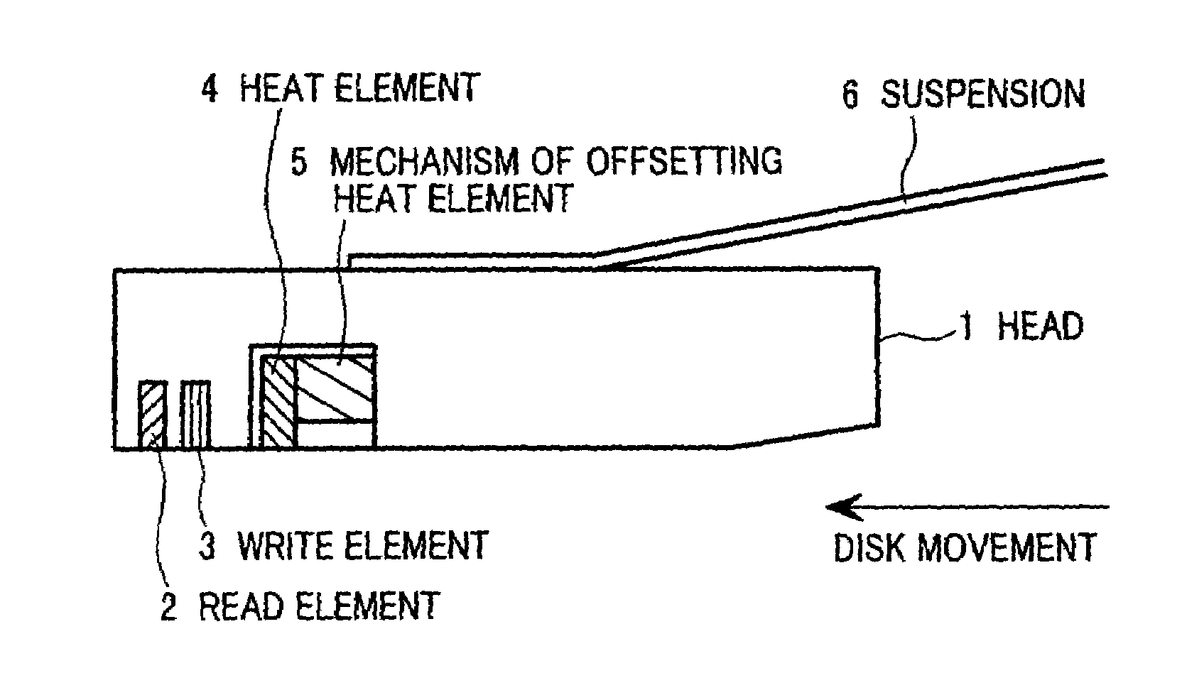
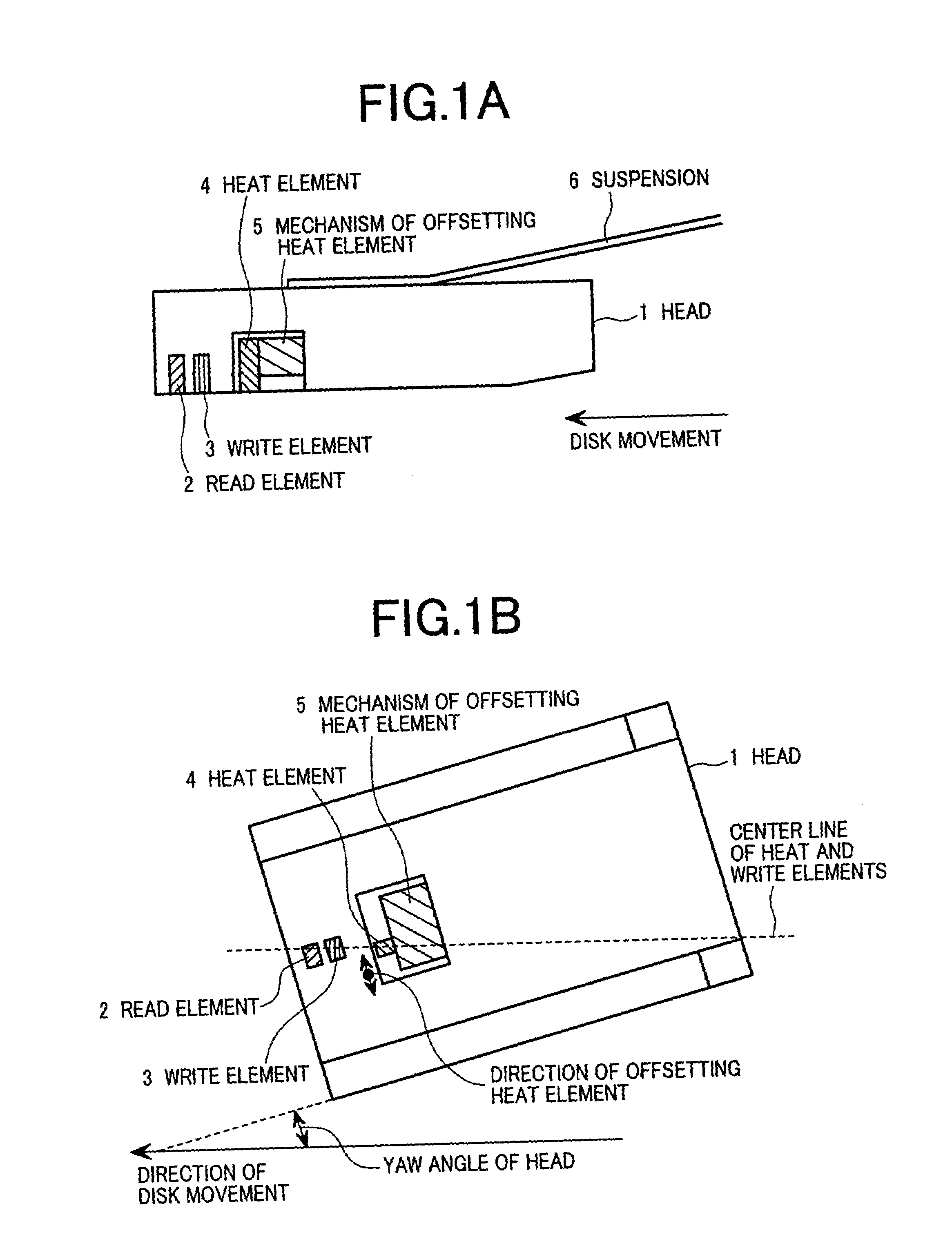
[0056]FIGS. 1A and 1B show the structure of a magnetic head according to an embodiment of the present invention. FIG. 1A shows a cross section of a head 1. The head 1, supported by a suspension 6, is floated on a rotating disk 12 with a constant interval from the disk. The disk 12 runs in a right-to-left direction in the figure. The head 1 has a read element 2 to detect magnetic information recorded on the disk, a write element 3 to generate a magnetic field to write the magnetic information on the disk, a heat element 4 to locally heat the disk for assisting recording of the magnetic information onto the disk, and a mechanism of offsetting heat element 5, to offset the heat element 4 in a slider width direction (or track width direction if a width direction of a magnetic width section recorded by the write element 3 is called a track width direction). Note that the offset direction does not necessarily correspond with the slider width direction, but there may be slight shift in acc...


PUM

PropertyMeasurementUnit
temperatureaaaaaaaaaa
magneticaaaaaaaaaa
magnetic fieldaaaaaaaaaa

Abstract

In a thermal assisted type magnetic disk apparatus having a head holding a heat element and a write element, in which coercivity of a disk is locally reduced by temperature-increasing the disk and writing is performed by the write element, along with a seek operation to move the head by a rotary actuator in a radial direction, a yaw angle is changed and a heat area and the write element are track-shifted. A mechanism to offset one of the heat area and the write element in a width direction of a slider, to array the heat element and the write element in a track running direction in correspondence with the yaw angle of the head.

Description

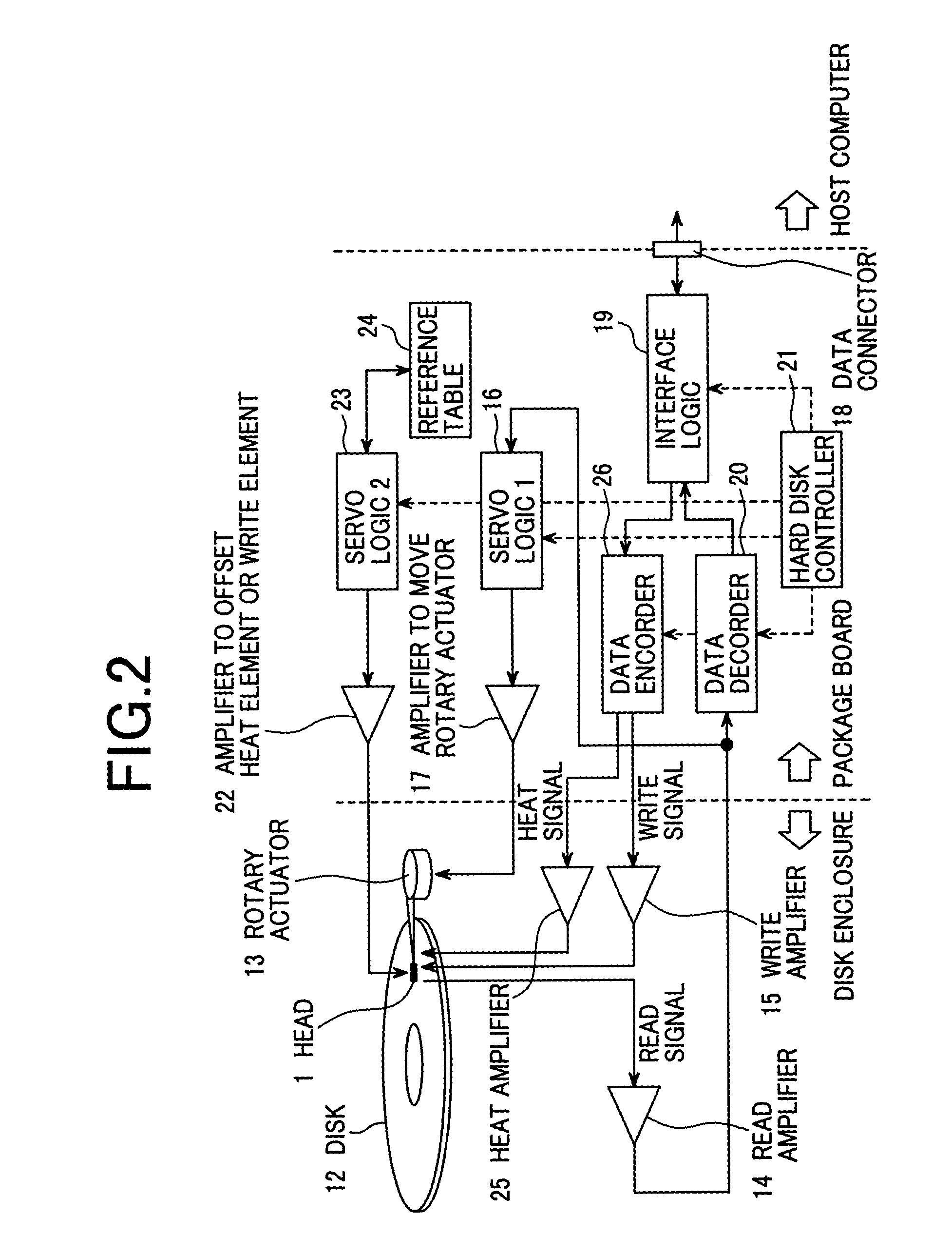
BACKGROUND OF THE INVENTION[0001]1. Field of the Invention[0002]The present invention relates to a disk apparatus for recording information, and more particularly, to a thermal assisted type magnetic recording apparatus in which the coercivity of a magnetic disk is locally reduced by a heat element for recording information in a high density, magnetic recording is performed using a write element in this position, and thereafter, the information is read from the magnetic disk using a read element.[0003]2. Description of the Related Art[0004]FIG. 3 is a top plan view of the inside of enclosure of a magnetic disk apparatus. FIG. 4 is a cross-sectional view of the magnetic disk apparatus. As shown in FIGS. 3 and 4, the magnetic disk apparatus has, as principal constituent elements, a head 30, a disk 31, a rotary actuator 13, a head amplifier 27, a package board 28 and the like. The disk 31, fixed to one rotary shaft, is rotate-driven by a spindle motor about a point A at a speed of 3000...

Claims


Application Information

Patent Timeline
Patent Type & Authority Patents(United States)
IPC IPC(8): G11B5/02G11B5/596G11B5/00G11B5/012G11B5/105G11B5/127G11B5/265G11B5/48G11B5/56G11B5/60G11B21/10G11B21/21
CPCG11B5/012G11B5/105G11B5/127G11B5/1272G11B5/56G11B5/6005G11B2005/0021G11B5/4886G11B2005/001G11B5/2654
Inventor HAMAGUCHI, TAKEHIKONAKAMURA, ATSUSHINISHIDA, YASUTAKAMOCHIZUKI, MASAFUMISAWAGUCHI, HIDEKI
Owner WESTERN DIGITAL TECH INC
Learn More