FPGA with register-intensive architecture

a register-intensive architecture and register-intensive technology, applied in the field of circuits, can solve the problems of the speed and complexity of signal processing of such logics that have tended to increase with time, and achieve the effect of reducing the consumption of general interconnect resources for supporting such circuit functions, eliminating or minimizing the consumption of general interconnect resources

Active Publication Date: 2006-04-11
LATTICE SEMICON CORP
View PDF9 Cites 262 Cited by
  • Summary
  • Abstract
  • Description
  • Claims
  • Application Information

AI Technical Summary

Benefits of technology

[0030](B.3) In accordance with a third detailed aspect of the present disclosure, block-dedicated feedback conductors and / or cluster-dedicated direct-connect conductors are used to compactly implement front- and / or back-end registered pipeline sections, dynamic multiplexers, barrel shifters, and / or other circuit functions so that consumption of general interconnect resources for supporting such circuit functions can be minimized.
[0031](B.4) In accordance with a fourth detailed aspect of the present disclosure, the multi-stage ISM's of one or more logic blocks are used for providing replication of selectively-acquired, local signals so that variable grain functions can be supported (more specifically, so that plural LUT's of a given logic block can be folded-together to a full or partial extent). Such in-ISM replication of signals may eliminate or minimize the consumption of general interconnect resources for providing such signal replication. The multi-stage ISM's of one or more logic blocks may alternatively or additionally be used for providing significance-type descrambling of signals so that consumption of general interconnect resources for providing such significance-type of re-scrambling of signals can be eliminated or minimized.
[0032](C) In accordance with a third aspect of the present disclosure, machine-implemented techniques (e.g., software techniques) are provided for generating FPGA configuration data that takes advantage of one or more of the register-intensive aspects, feedthroughs-intensive aspects, multi-stage ISM aspects, and / or other aspects of the FPGA structurings disclosed herein.

Problems solved by technology

Historically speaking, it may be observed that within integrated circuits (IC's) the density of programmably-reconfigurable, digital logic circuitry has continued to increase, and the signal-processing speed and complexity of such logic has also tended to increase with time.

Method used


Image

  • FPGA with register-intensive architecture
  • FPGA with register-intensive architecture
  • FPGA with register-intensive architecture

Examples


embodiment 200

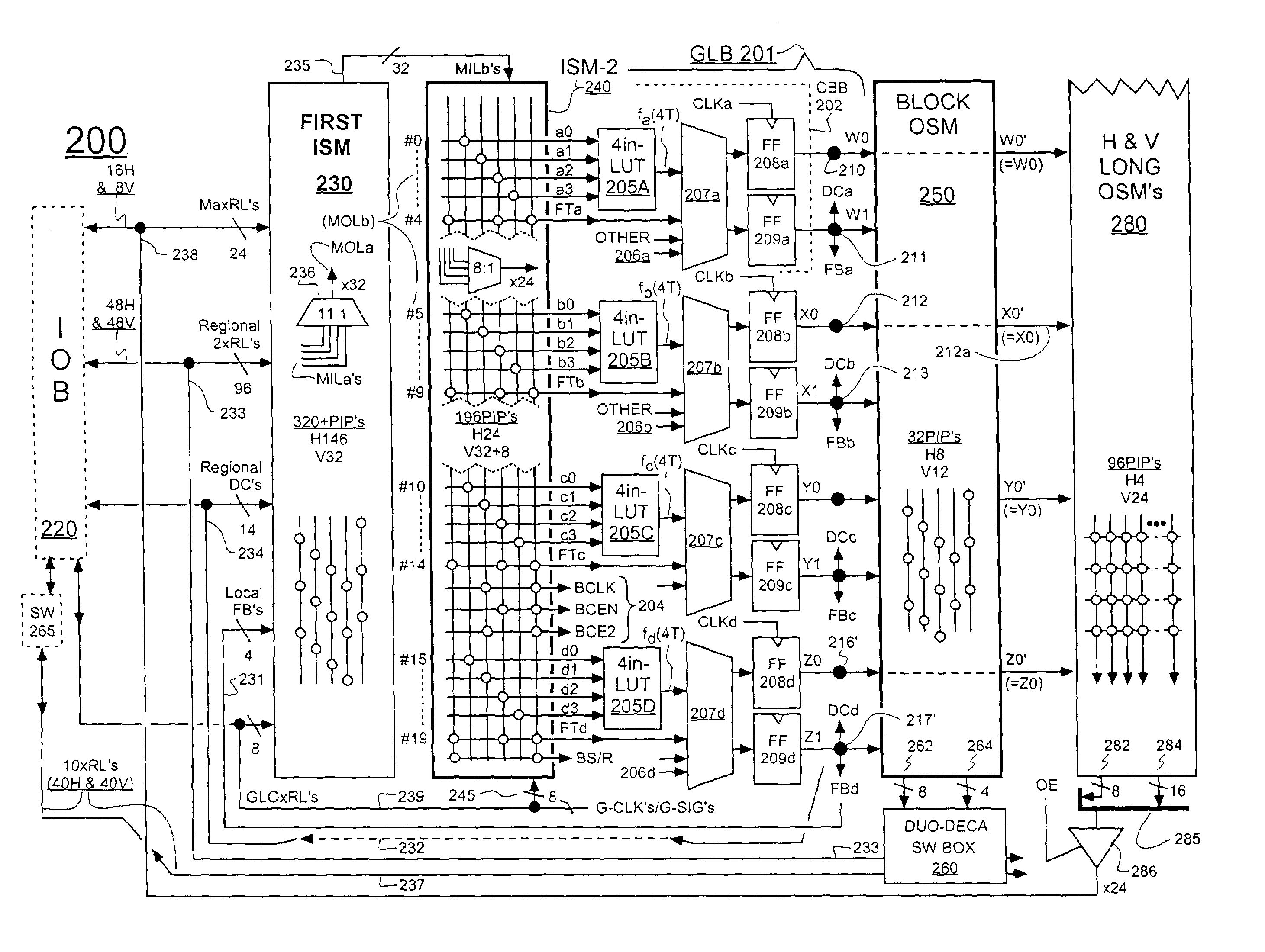
[0154]In the illustrated embodiment, the Block OSM 250 (BOSM) feeds into a so-called, duo-deca switchbox 260. The latter switchbox 260 can be user-programmed to route the BOSM's output signals 262 and 264 respectively onto duo-reach general interconnect lines (2xRL's) 233 and onto deca-reach general interconnect lines (10xRL's) 237. Additionally, the duo-deca switchbox 260 can programmably route signals between various ones of the 2xRL and 10xRL lines passing through that switchbox 260. For the given embodiment 200, the 1 xRL lines (237) do not directly connect to the multi-stage input-signals acquiring means (e.g., 230–240). Instead, signals that are to travel intermediate-length distances by way of the 10xRL lines, must use the duo-reach lines (2xRL's) of certain ones of adjacent logic tiles (see 390a–390c of FIG. 3B) essentially as entrance ramps and exit ramps for correspondingly getting onto and exiting from the deca-reach highway lines, where this entering and exiting occurs w...

embodiment 300

[0220]As can be further seen in FIG. 3A, besides the 2xRL lines and the MaxRL lines, the local FB's and DC's (301f as well as the global-reach conductors (301g) define additional, adjacent interconnect lines (AIL's) of ISM blocks such as 324. Signals from the various AIL's of a given ISM block can be selectively acquired by the ISM block (e.g., 324) and fed into the corresponding GLB (e.g., 320) for processing therein. GLB outputs may then returned to the AIL's for local continuation (e.g., via the FB's and / or DC's) and / or for general continuation (e.g., via the local duo-deca switchbox, and then through the 2xRL and / or 10xRL lines) and / or long distance continuation (e.g., via the MaxRL lines). The horizontal and vertical, longlines output switch matrices (LOSM's) are organized to service respective horizontal and vertical sequences of four GLB's each. Part of a vertical one of such sequences of GLB's is shown in FIG. 3A as dashed box 381. Part of a horizontal one of such sequences ...

embodiment 401

[0268]For purposes of continuity, ISM stages −1 and −2 are schematically represented as 401′ and 402′, respectively. The illustrated ISM-2 stage, 402′ may be the same as the 402 embodiment shown in FIG. 4A or a different embodiment that conforms with the principles of the present disclosure. Similarly, the illustrated ISM-1 stage shown at 401′ in FIG. 4B may be the same as the specific stage-1 embodiment 401 shown in FIG. 4C or another embodiment which conforms with the principles of the present disclosure.

[0269]For the specific GLB controls generator 400B′ shown in FIG. 4B, some of the generated control signals such as generally identified by 403 are common to the associated GLB 404′. Some others of the control signals such as generally identified by 405 are common to a given register pair (e.g., 408a*–409a*) of the associated GLB 404′. Yet other control signals such as generally identified by 407 are specific to the operations of a specific state-storing register (e.g., 408a*) wit...


PUM


Abstract

Field programmable gate arrays (FPGA's) may be structured in accordance with the disclosure to have a register-intensive architecture that provides, for each of plural function-spawning LookUp Tables (e.g. a 4-input, base LUT's) within a logic block, a plurality of in-block accessible registers. A register-feeding multiplexer means may be provided for allowing each of the plural registers to equivalently capture and store a result signal output by the corresponding, base LUT of the plural registers. Registerable, primary and secondary feedthroughs may be provided for each base LUT so that locally-acquired input signals of the LUT may be fed-through to the corresponding, in-block registers for register-recovery purposes without fully consuming (wasting) the lookup resources of the associated, base LUT. A multi-stage, input switch matrix (ISM) may be further provided for acquiring and routing input signals from adjacent, block-interconnect lines (AIL's) and/or block-intra-connect lines (e.g., FB's) to the base LUT's and/or their respective, registerable feedthroughs. Techniques are disclosed for utilizing the many in-block registers and/or the registerable feedthroughs and/or the multi-stage ISM's for efficiently implementing various circuit designs by appropriately configuring such register-intensive FPGA's.

Description

FIELD OF DISCLOSURE[0001]The present disclosure of invention relates generally to circuits having repeated configurable logic and configurable interconnect structures provided therein and methods for configuring the same. Examples of such circuits include Field Programmable Gate Arrays (FPGA's).[0002]The disclosure relates more specifically to problems concerning efficient, programmable implementation of synchronous digital designs while using different types of programmably-selectable interconnect resources and / or logic resources such as those provided within an integrated circuit monolith that contains a programmable logic circuit such as a field programmable gate array (FPGA).CROSS REFERENCE TO CO-OWNED APPLICATIONS[0003]The following copending U.S. patent applications are owned by the owner of the present application, and their disclosures are incorporated herein by reference:[0004](A) Ser. No. 09 / 692,694 filed Oct. 18, 2000 by Richard T. Cote, et al. and originally entitled, “S...

Claims


Application Information

Patent Timeline
Patent Type & Authority Patents(United States)
IPC IPC(8): G06F17/50H03K19/177
CPCG06F17/5054H03K19/17728H03K19/17736H03K19/17784H01L2924/0002H01L2924/00G06F30/34
Inventor AGRAWAL, OM P.SHARPE-GEISLER, BRADLEY A.
Owner LATTICE SEMICON CORP
Why Eureka
Try Eureka