
Cooling system for skid steer loader including fan assembly mounted to engine

a technology for skid steer loaders and cooling systems, which is applied in the direction of machines/engines, cycles, transportation and packaging, etc., can solve the problems of loss of fan efficiency and relatively bulky cooling systems, and achieve the effect of increasing cooling efficiency

Active Publication Date: 2006-04-18
BLUE LEAF I P INC +1
View PDF14 Cites 10 Cited by
  • Summary
  • Abstract
  • Description
  • Claims
  • Application Information

AI Technical Summary

Benefits of technology

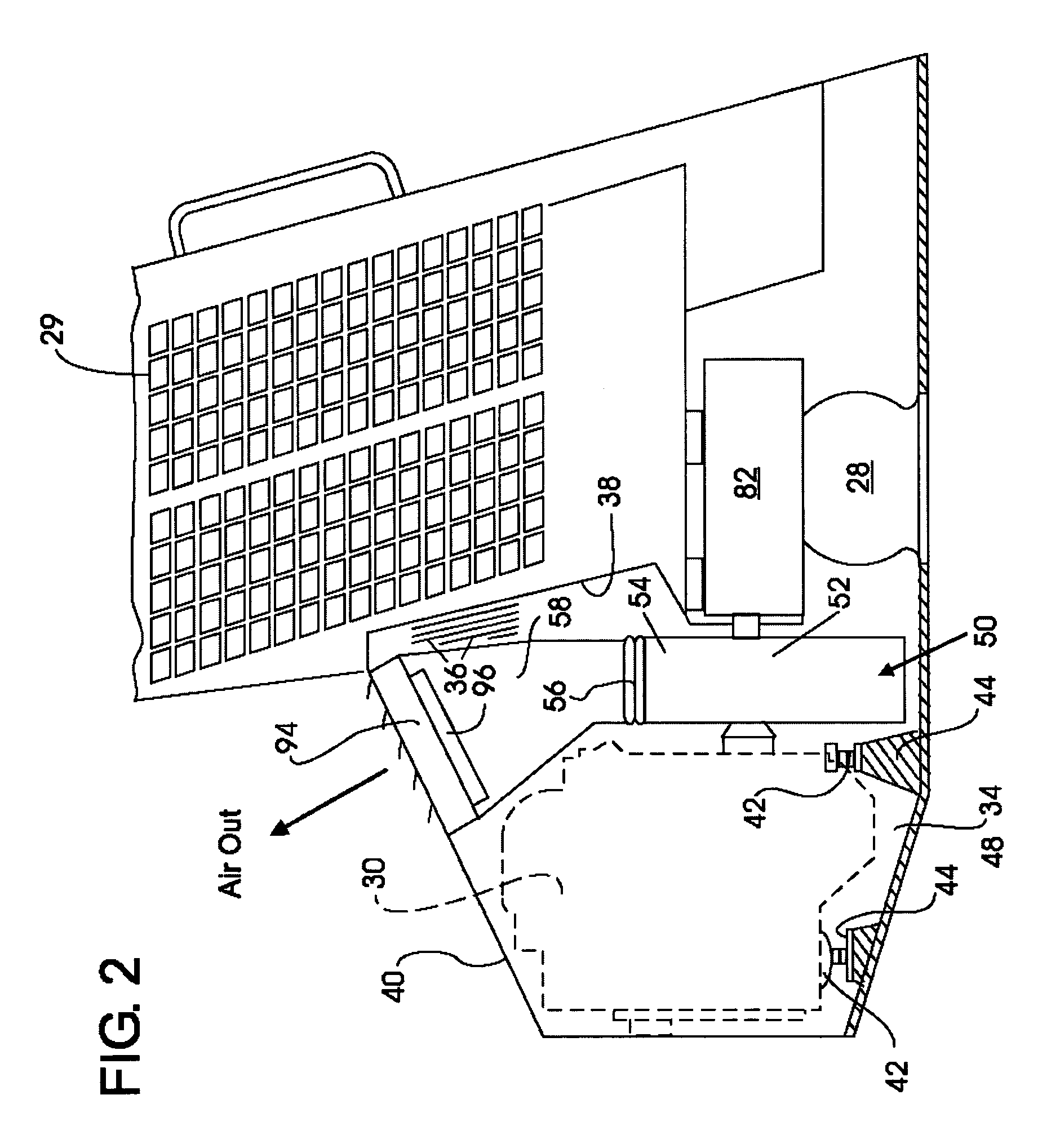
The present invention provides an improved cooling system for a work vehicle, such as a skid steer loader, to increase cooling efficiency. The system includes a fan assembly with a fan and a shroud that are rigidly mounted to the engine, creating negative pressure in the engine compartment. The fan draws ambient air into the compartment, carries it over the engine, and pushes it out through a cooler for the engine cooling liquid. A flexible coupling is provided between the fan assembly and the coolers to prevent vibration. The cooling system is more efficient and compact, improving operator visibility to the rear of the vehicle.

Problems solved by technology

This so-called “engine cooling stack” provides a relatively bulky cooling system.
This results in a loss of efficiency of the fan and requires a larger fan to maintain proper cooling of the engine coolant liquid cooler and oil cooler.

Method used


Image

  • Cooling system for skid steer loader including fan assembly mounted to engine
  • Cooling system for skid steer loader including fan assembly mounted to engine
  • Cooling system for skid steer loader including fan assembly mounted to engine

Examples


Embodiment Construction

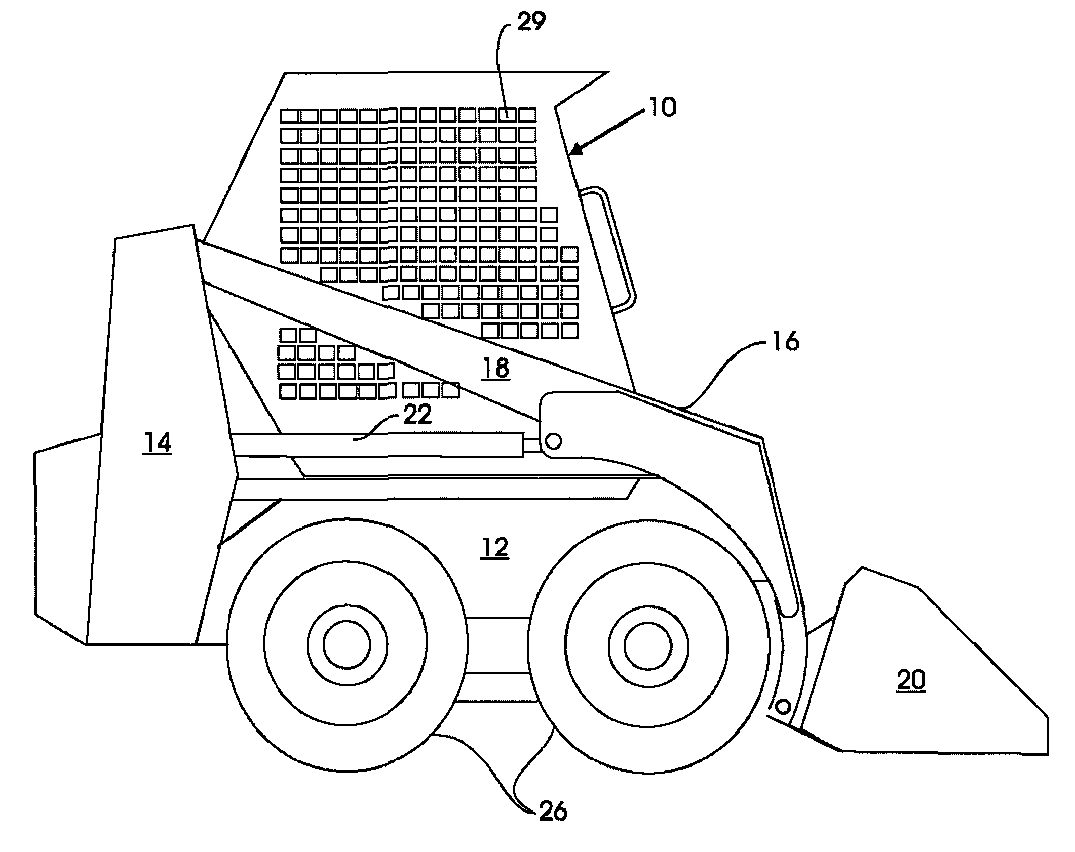
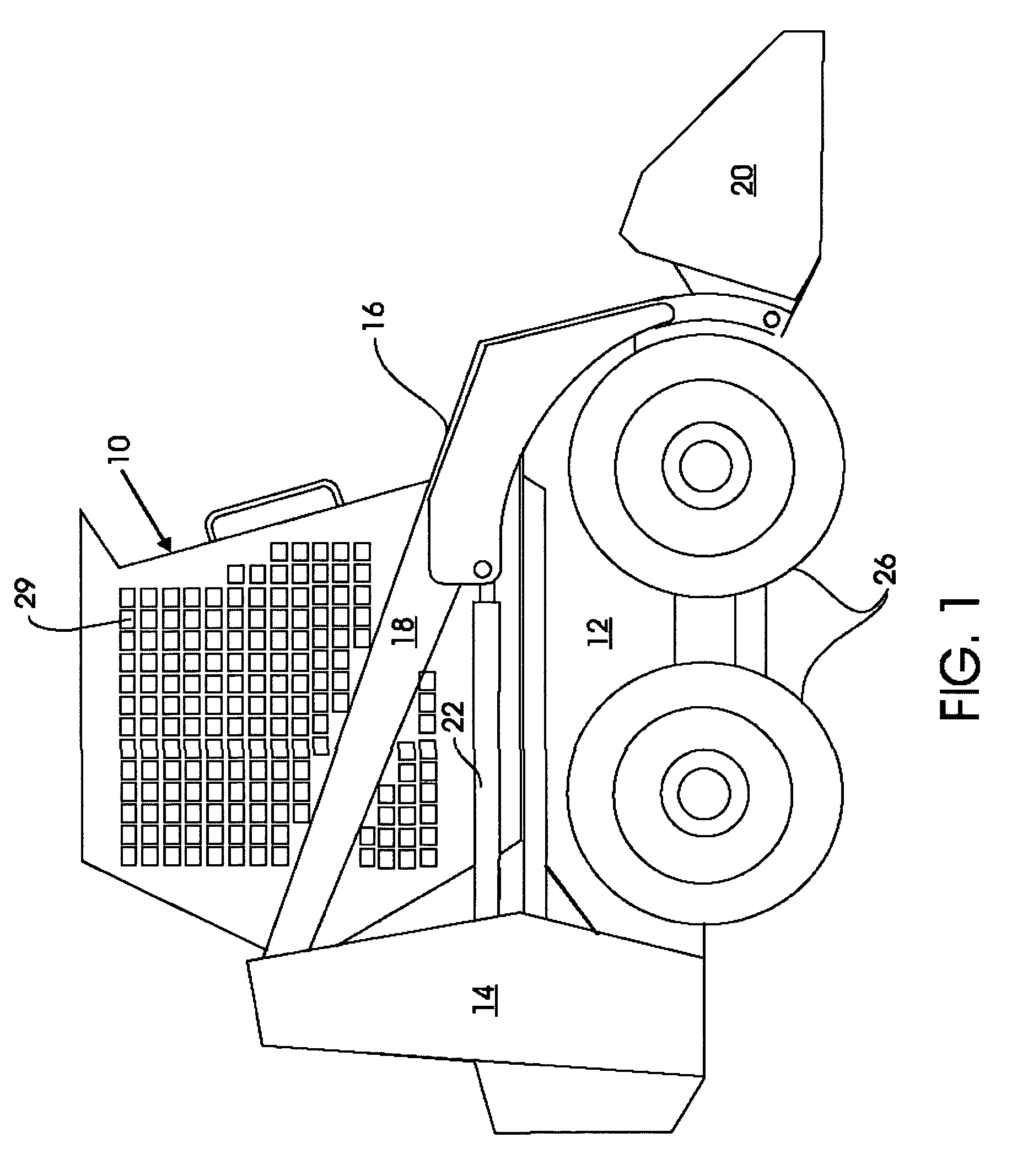
[0015]Referring now to FIG. 1, a loader type work vehicle, in the illustrated instance a skid-steer vehicle 10 including a body portion 12 has mounted on opposite sides of the body portion rear uprights 14. The uprights 14 carry at an upper end portion thereof a loader arm assembly 16 pivotally mounted thereon and comprising oppositely disposed loader arms 18. The loader arms 18 extend outwardly at the front end of the vehicle to pivotally engage a work lifting device, in the illustrated instance a bucket 20. While two loader arms are shown, a single loader arm may be used. Lift cylinders 22 control the loader arms 18 and a tilt cylinder (not shown) controls the bucket 20. Two sets of wheels 26 are provided on opposite sides of the vehicle 10. Each set of wheels 26 is controlled by an independent drive mechanism 28 (schematically shown in FIG. 2) controlled in a conventional manner by individual hand levers (not shown) provided in the driver's compartment 29. The skid-steer independ...


PUM


Abstract

The cooling system of a skid-steer loader provides for heat exchangers, e.g. liquid, oil coolers, mounted in the upper portion of an engine compartment and in direct communication with a forced air flow. Circulating air is drawn into the engine compartment from the rear, is carried over the engine and is blown out through the heat exchangers to cool the liquid within the heat exchangers. The housing of a centrifugal fan is rigidly coupled to the engine block and the fan is also directly coupled to the engine flywheel. This allows for closer tolerances between the fan and its housing which results in higher efficiency because this dual coupling to the engine inhibits differential vibration between the fan and the housing. Interconnection between the heat exchangers and fan housing is via a flexible bellows and an air diffuser.

Description

CROSS-REFERENCE TO RELATED APPLICATIONS[0001]None.BACKGROUND OF THE INVENTION[0002]The present invention relates generally to the field of work vehicles such as construction and agricultural vehicles, and more particularly to vehicles commonly referred to as skid-steer loaders.[0003]A skid-steer vehicle is a compact, highly maneuverable vehicle which employs driving mechanisms on opposite sides of the vehicle for independently driving each set of wheels mounted thereon. In a skid-steer vehicle the engine is mounted in the rear. The traditional cooling system of prior art skid-steer vehicles aligns or stacks the cooling system in serial relationship with the engine. That is, the fan, the engine coolant liquid cooler (i.e. radiator) and the oil cooler are axially aligned behind the engine. This so-called “engine cooling stack” provides a relatively bulky cooling system.[0004]While the structure shown in U.S. Pat. No. 4,117,902, issued on Oct. 3, 1978 to Henline et al., has helped to m...

Claims


Application Information

Patent Timeline
Patent Type & Authority Patents(United States)
IPC IPC(8): F01P7/02
CPCF01P5/04F04D25/02F01P5/06F01P2001/005
Inventor WAGNER, EDWARD L.
Owner BLUE LEAF I P INC
Learn More