Vibration damping tool

a vibration damping and tool body technology, applied in the direction of shock absorbers, machine supports, manufacturing tools, etc., can solve the problems of deteriorating the surface roughness of the processed surface of the material, breaking the tool body itself, and difficult to generate resonance, so as to achieve the effect of suppressing chatter vibration

Inactive Publication Date: 2006-04-18
MITSUBISHI MATERIALS CORP
View PDF21 Cites 23 Cited by
  • Summary
  • Abstract
  • Description
  • Claims
  • Application Information

AI Technical Summary

Benefits of technology

[0013]The present invention was conceived in view of the above problems and it is an aim thereof to provide a vibration damping tool that is able to suppress chatter vibration utilizing a simple structure that is not affected by heat generated during cutting processing, and that enables the ratio L / D of the projecting length L relative to the diameter D of the tool body to be enlarged further.

Problems solved by technology

This chatter vibration worsens as the ratio L / D, which is the length L that the tool body projects outwards relative to the diameter D of the tool body, increases, leading to a deterioration in the surface roughness of the processed surface of the material being cut, or in severe cases, may lead to a breakage of the tool body itself.
Therefore, an upper limit value of approximately 3 to 4 is set for the ratio L / D, which has created problems particularly when an increase in the ratio L / D is desired such as, for example, in deep groove processing of a metal die or in boring processing using a boring bar.
In tools such as these, by increasing the rigidity of the tool body, the aim is to raise the undamped natural frequency of the tool body and thereby make it difficult for resonance to be generated.
However, because chatter vibration increases as the ratio L / D increases, a fundamental solution has hitherto not been possible.
However, the viscous fluid 103 that is used as a damping element in the dynamic vibration absorber has a drawback in that it is easily affected by heat so that the viscosity thereof changes.
When heat that is generated during cutting is transmitted to the viscous fluid 103 and the temperature of the viscous fluid 103 itself increases, the viscosity deteriorates and the damping affect also deteriorates causing concern that chatter vibration will not be able to be suppressed.
Furthermore, because a structure is employed in which the weight member 102 is supported by the elastic members 101 and 101, when a tool body 100 that is provided with this type of dynamic vibration absorber is used as a rotation cutting tool, because eccentricity is generated in the weight member 102 as a result of the rotation of the tool body 100, problems such as it becoming necessary to lower the rotation speed occur which mean that this structure is not suitable for use as a rotation cutting tool.

Method used


Image

  • Vibration damping tool
  • Vibration damping tool
  • Vibration damping tool

Examples


first embodiment

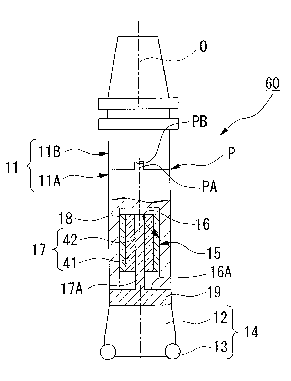
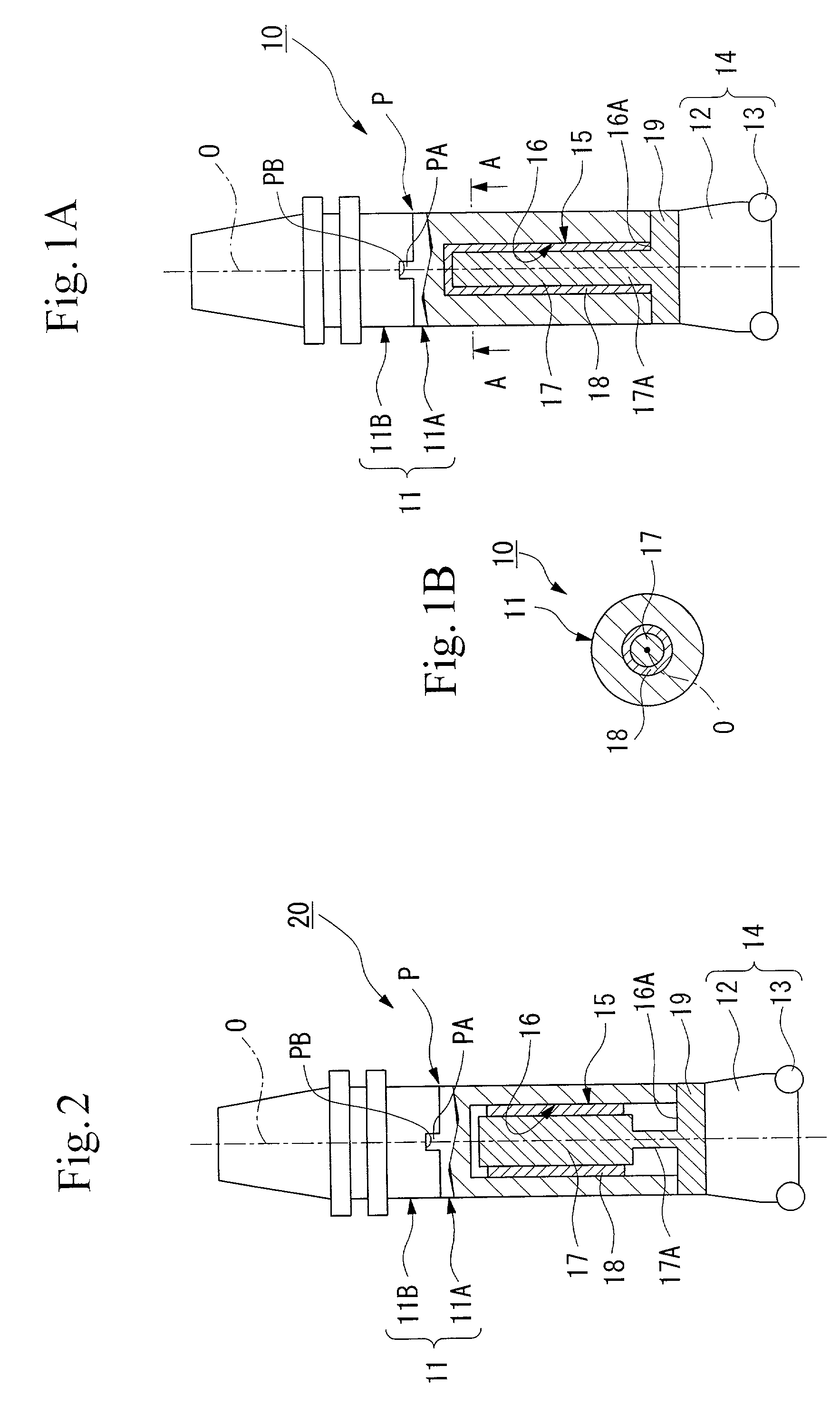
[0049]As is shown in FIG. 1, the vibration damping tool (referred to below as a damping tool) 10 is a rotation cutting tool that is formed mainly by a tool body 11 and a head portion 14 (i.e., a processing means). The tool body 11 is made from steel, for example, and has a base end supported in a cantilever fashion by a gripping portion of a machine tool. The tool body 11 has a substantially cylindrical configuration and is rotated around an axis O. The head portion 14 has a plurality of inserts 13 mounted on the outer periphery of a distal end of a head body 12.

[0050]As is shown in FIG. 1, the head portion 14 is removably mounted by a connecting screw (not shown) on the distal end portion of the tool body 11 coaxially with the axis O. The head portion 14 is mounted such that a cutting edge of each insert 13 protrudes on the distal end side and also on the outer peripheral side of the damping tool 10.

[0051]A substantially cylindrically shaped hollow portion 15 is formed inside the ...

second embodiment

[0080]As is shown in FIG. 2, in the damping tool 20 the end 17A of the weight member 17 presents a shaft portion having a narrow diameter that is coaxial with the axis O of the tool body 11. The weight member 17 is connected to the inner wall surface 16A of the distal end side of the hollow portion 15 by this end 17A presenting the narrow diameter shaft portion. In this damping tool 20, the visco-elastic body 18 fills a gap between an outer peripheral surface that is shaped as a circular cylinder of the weight member 17 other than the end 17A and the inner wall surface 16 of the hollow portion 15, however, it is also possible to decrease the amount thereof used to fill this gap or to fill the rest of the gap depending on the design of the dynamic vibration absorber.

[0081]According to the damping tool 20 having the above described structure, flexure is easily generated in the small diameter shaft portion (i.e., the end 17A) of the weight member 17 so that vibration is easily excited...

third embodiment

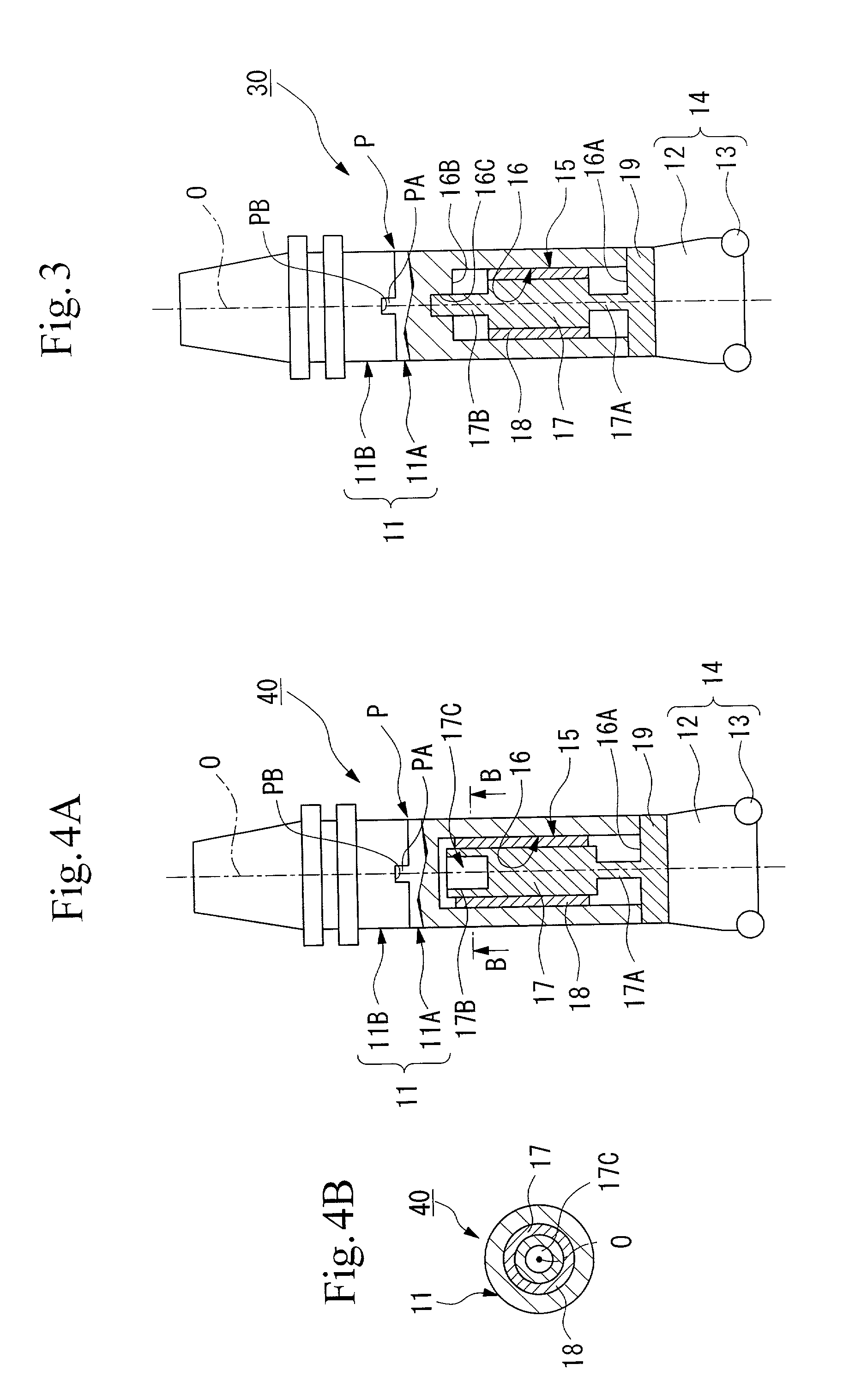
[0083]As is shown in FIG. 3, in the damping tool 30 the end 17A of the weight member 17 presents a shaft portion having a narrow diameter and is also fixed to the inner wall surface 16A on the distal end side of the hollow portion 15. In addition, the other end 17B on the opposite side from the end 17A also presents a shaft portion having a narrow diameter and is also fixed to the inner wall surface 16B on the base end side of the hollow portion 15. Here, when the weight member 17 and the visco-elastic body 18 are inserted in the hollow portion 15 together with the base plate 19, the end 17B of the weight member 17 is fitted together with a support hole 16C provided in the inner wall surface 16B on the base end side by being inserted into this hole.

[0084]According to the damping tool 30 having the above described structure, both ends 17A and 17B of the weight member 17 are formed having narrow diameter shaft portions and the weight member 17 is fixed integrally to the tool body 11 ...


PUM

PropertyMeasurementUnit
elongationaaaaaaaaaa
tensile strengthaaaaaaaaaa
Young's modulusaaaaaaaaaa

Abstract

A vibration damping tool having the following structure is provided. In the vibration damping tool, a hollow portion is formed in the interior of the distal end portion of a tool body and one end of a weight member is connected to the inner wall surface of the distal end side of this hollow portion. A gap created between the outer peripheral surface of the weight member and the inner wall surface of the hollow portion is filled with a visco-elastic body. The one end of the weight member is formed as a narrow diameter shaft portion. The tool body can be divided into two and freely removed from and reattached at a dividing surface located on the base end side of the hollow portion. A hole portion is formed inside the other end of the weight member by hollowing out the interior thereof. Chatter vibration is thus absorbed using a simple structure without there being any effects from heat generated during cutting processing.

Description

BACKGROUND OF THE INVENTION[0001]1. Field of the Invention[0002]The present invention relates to a vibration damping tool that is able to suppress vibration generated during a process to machine cut a material.[0003]2. Description of the Related Art[0004]Conventionally, a head portion on which inserts are mounted is attached to a tool body, for example, such as an arbor. A material to be cut may be cut by moving the tool body forward while rotating it around an axis. Alternatively, an insert may be attached to the distal end of a tool body such as a boring bar and the material to be cut may be cut as it is rotated around an axis.[0005]At this time, the base end of the tool body is supported in a cantilever manner by a gripping portion of a machine tool and when a cutting processing is performed on the material to be cut using the cutting edge of an insert, resonance is created from the natural vibration of the tool that derives from the projecting length of the tool from the grippin...

Claims


Application Information

Patent Timeline
Patent Type & Authority Patents(United States)
IPC IPC(8): F16M1/00B23B29/02
CPCB23B29/022Y10T408/76Y10T82/2585Y10T409/304312B23B29/02
Inventor TAKAHASHI, HIDEBUMIISHIKAWA, YOICHI
Owner MITSUBISHI MATERIALS CORP
Why Eureka
Try Eureka