Method and apparatus for transferring a thin plate

a technology of thin plate and transfer method, which is applied in the direction of instruments, charging manipulation, furniture, etc., can solve the problems of large amount of cost, difficult maintenance of the device assembly, and delicate adjustment of the control circuit, so as to facilitate the alignment of the holding claws, facilitate maintenance, and facilitate delicate adjustment

Inactive Publication Date: 2006-04-18
PANASONIC CORP
View PDF1 Cites 21 Cited by
  • Summary
  • Abstract
  • Description
  • Claims
  • Application Information

AI Technical Summary

Benefits of technology

[0015]In view of the above conventional problems, an object of the present invention is to provide a method and apparatus for transferring a thin plate, by which a thin plate, which is extremely thin and easy to warp, is held and reliably and rapidly attached to an attachment section having a small holding margin without the adhesion of dust and the like.
[0017]Using the two transfer arms, one of which is for mounting the thin plate and the other is for dismounting thereof, makes it possible to efficiently receive the thin plate from a transfer position and transfer it thereto.
[0019]In a method for transferring a thin plate according to the present invention, three or more grasping claws provided in a transfer arm grasp the periphery of a thin plate to move it to a predetermined transfer position. Each grasping claw of the transfer arm is brought close to three or more holding claws provided in the transfer position. The transfer arm is moved in such a manner that a first contact face, which is provided in the transfer arm so as to move together with each grasping claw, makes closely contact with a second contact face provided in the transfer position corresponding to the first contact face. Then, the grasping claws are gradually moved by elastic biasing force to transfer the thin plate from the grasping claws of the transfer arm to the holding claws of the transfer position with the first and second contact faces being in contact with each other. If the position of the transfer arm deviates due to the vibration and the long-term use of a unit, it is possible to surely transfer the thin plate to the holding claws of the transfer position with avoiding contact between the grasping claws and the holding claws, without a complex and expensive control device.
[0021]In a method for transferring a thin plate according to the present invention, three or more grasping claws provided in a transfer arm grasp the periphery of the thin plate to move the thin plate to a predetermined transfer position. The periphery of the thin plate is held with three or more holding claws in the transfer position. A V-shaped holding groove is concentrically formed in the periphery of the holding claw, and the holding claw rotates about a shaft the position of which deviates from the center of the V-shaped holding groove, for the purpose of adjusting the position of said thin plate with rotation. When the holding claw is worn out due to the long-term use and the like, it is possible to easily align the holding claws, the position of which has to be delicately adjusted, with adjusting the position in a rotational direction. This also makes maintenance easy.

Problems solved by technology

Thus, there is a problem that the dust and the like falling down from the hand section tends to adhere to the wafer which is required to be clean.
Thus, a control circuit which requires delicate adjustment is necessary for the purpose.
Therefore, there are problems that a large amount of cost is necessary to adjust the assembly of the device, and the maintenance thereof is difficult.
It is difficult to make an identical part with precision to less than 0.1 mm, due to the characteristics of the plastic.
Thus, there is a problem that man-hour for adjustment increases.
In this way, the adjustment of the transfer unit including the actuator is troublesome in the conventional transfer unit.
The conventional transfer unit also has the high risk of adhesion of dust on the top surface of the wafer.
Furthermore, there is a problem that it is difficult to attach and adjust the wafer holder claws in exchanging.

Method used


Image

  • Method and apparatus for transferring a thin plate
  • Method and apparatus for transferring a thin plate
  • Method and apparatus for transferring a thin plate

Examples


Embodiment Construction

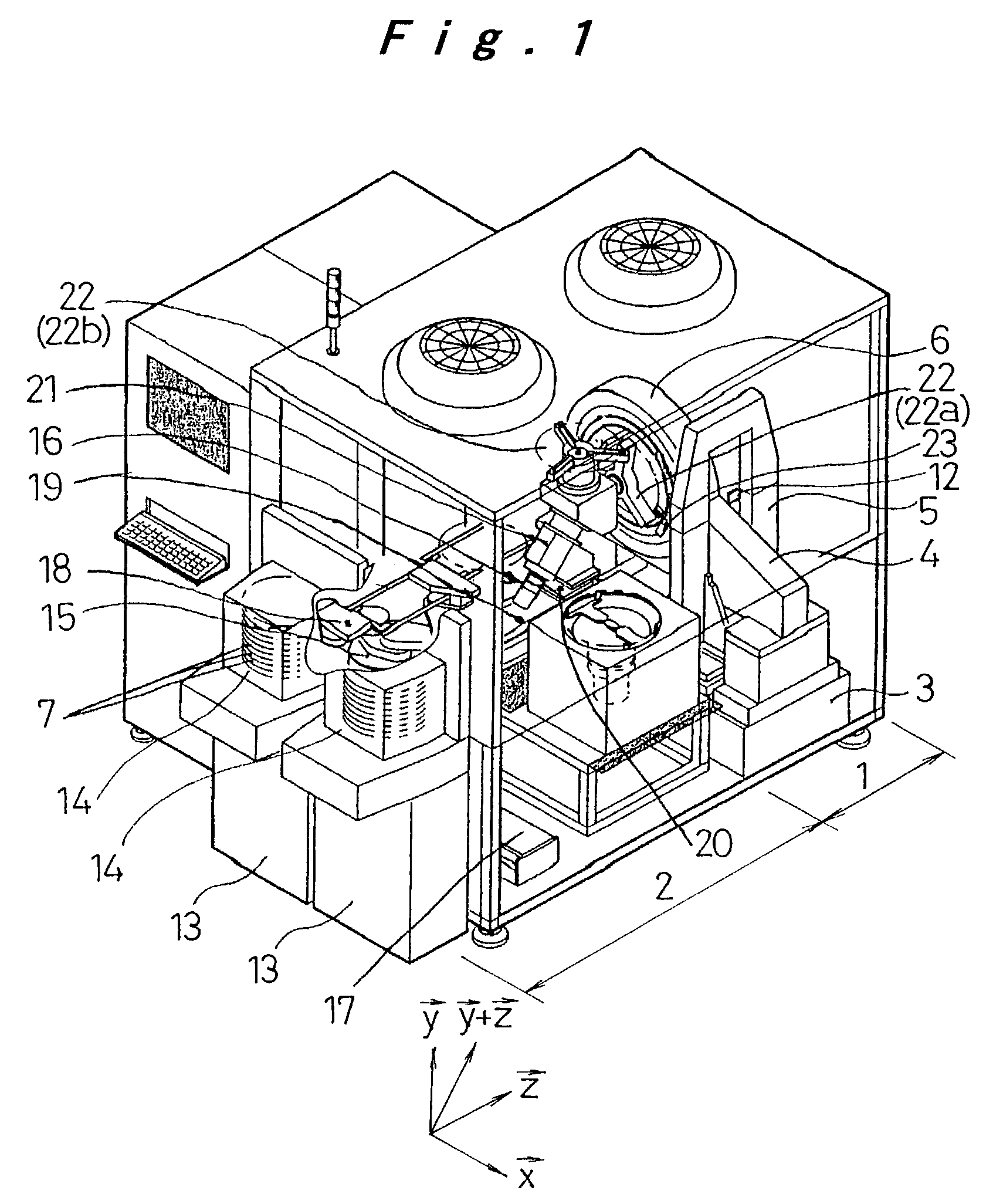
[0042]An embodiment of a transfer unit for use in transferring a thin plate according to the present invention will be hereinafter described with reference to FIGS. 1 to 8B. This embodiment is a concrete example of the present invention, and does not limit the technical scope of the present invention.

[0043]FIG. 1 shows a measuring device for flatness of a semiconductor wafer in which a transfer unit of a thin plate according to the present invention is installed. The measuring device comprises a main unit 1 and a transfer unit 2.

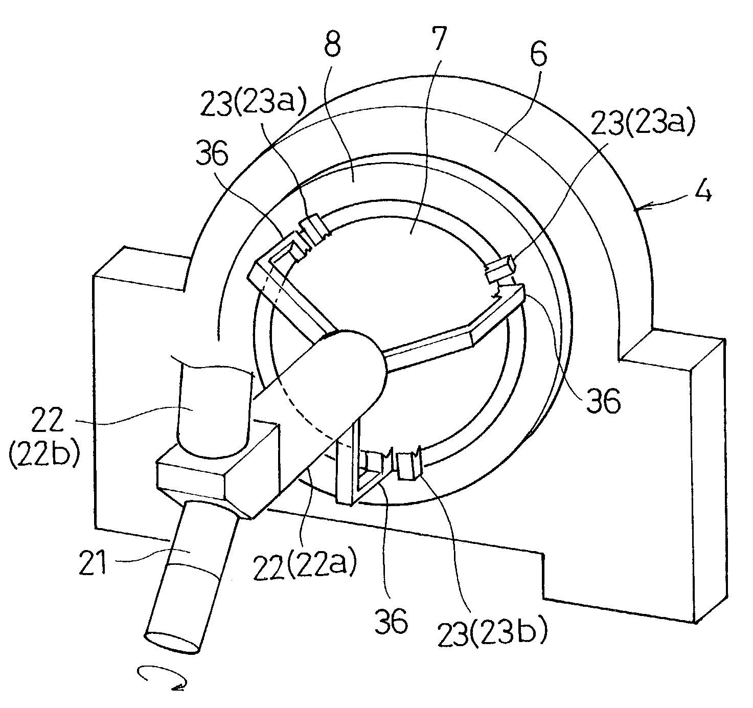
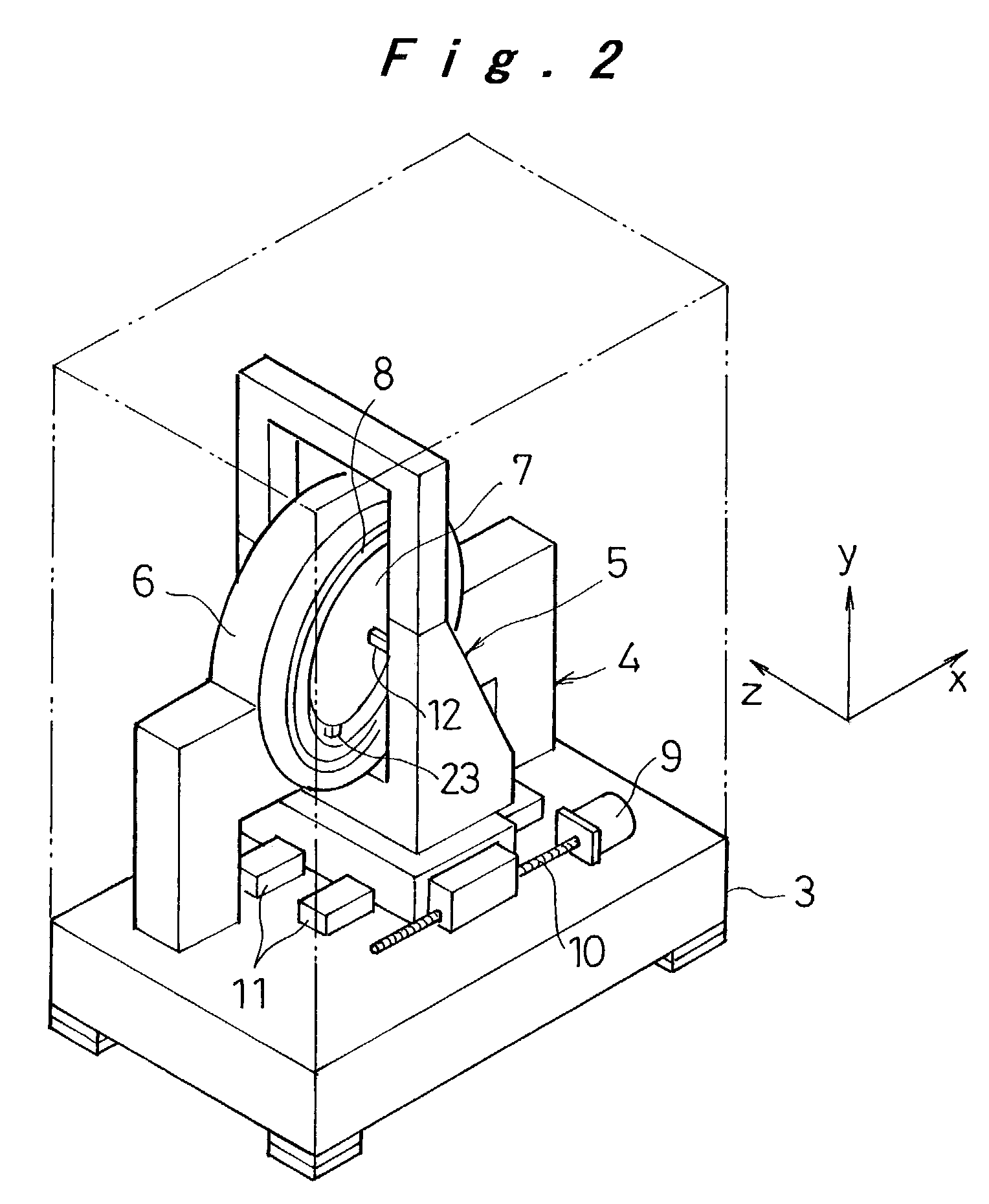
[0044]Referring to FIG. 2, the main unit 1 is provided with a wafer holding stage 4 and a sensor movement stage 5 which are disposed on a base 3. The wafer holding stage 4 has a direct drive motor 6, and a circular spindle 8 which are rotated by the direct drive motor 6 on an X-Y plane. A wafer 7 is held on the inner radius of the spindle 8. The sensor movement stage 5 is movable by means of a ball screw 10 rotated by a motor 9 along a guide 11 in an X-axis ...


PUM


Abstract

A method for transferring a thin plate is provided, in which three or more grasping claws of a transfer arm grasp the periphery of the thin plate in order to transfer it to a predetermined transfer position, and three or more holding claws hold the periphery of the thin plate in the transfer position. The transfer arm rotates about a shaft which is in a direction of a vector sum of a first vector perpendicular to a surface of the thin plate before transfer, and a second vector perpendicular to the surface of the thin plate after the transfer, to transfer the thin plate with changing the posture thereof.

Description

BACKGROUND OF THE INVENTION[0001]1. Field of the Invention[0002]The present invention relates to a method and apparatus for transferring a thin plate for use in transferring a thin plate such as a wafer for manufacturing a semiconductor, a substrate for a magnetic disc, and the like.[0003]2. Description of the Related Art[0004]A wafer for manufacturing a semiconductor comprises a thin plate of silicon and the like. Semiconductor devices and electronic circuits are made on the surface of a wafer with photo engraving technology and various types of microfabrication technology. In processing such a wafer, it is necessary to securely transfer the wafer with holding only the vicinity of the periphery thereof, in order to prevent a defect and quality deficiency from occurring due to dust and the like adhering to the surface thereof, and to increase an effective chip area.[0005]Recently, for the purpose of realizing finer-line processes of semiconductor devices and improving productivity t...

Claims


Application Information

Patent Timeline
Patent Type & Authority Patents(United States)
IPC IPC(8): B25J17/02B25J15/10B65G49/07G01B11/24H01L21/50H01L21/66H01L21/677H01L21/68H01L21/683H01L21/687
CPCB25J15/103H01L21/68707H01L21/67742Y10T74/20335H01L21/68
Inventor KUBO, KEISHIYOSHIZUMI, KEIICHITAKEUCHI, HIROYUKIHANDA, KOJIKASSAI, TAKAAKI
Owner PANASONIC CORP
Why Eureka
Try Eureka