Method and apparatus for distal targeting of locking screws in intramedullary nails

a locking screw and intramedullary nail technology, applied in the field of system for aligning locking screws with openings in intramedullary nails, can solve the problems of inability to consistently identify the position and angular orientation of the drill bit, long-term consequences of x-ray accumulation, and difficulty in achieving the effect of reducing the number of screws in the drill bit passing through the transverse hole, reducing the number of screws in the drill bit, and simplifying the formation of the integral uni

Inactive Publication Date: 2006-04-18
DEPUY PROD INC
View PDF21 Cites 45 Cited by
  • Summary
  • Abstract
  • Description
  • Claims
  • Application Information

AI Technical Summary

Benefits of technology

[0009]The present invention addresses the above needs, as well as others, with a probe having an elongated member and a first and a second drive coil mounted to the elongated member, the first and the second drive coils being proximate one another and being oriented so that a magnetic field generated by the first drive coil is orthogonal to a magnetic field generated by the second drive coil. The drive coils are place proximate to one another so that the origin of the magnetic fields emitted by the drive coils appear to be the same from a sensor associated with a surgeon's drill. Preferably, the drive coils are separated by a distance of approximately 0.100 inches or less. This close proximity permits the integral unit containing the two drive coils to be constructed by orienting the drive coils in perpendicular arrangement in close proximity to one another and then encapsulating them in the polymeric resin. This construction simplifies the formation of the integral unit because the short conduit section is no longer required to stiffen the integral unit. Furthermore, greater stress is required at the junction of the integral unit and main conduit before the integral unit is separated from the main conduit. Thus, probe construction is simplified and the probe has greater mechanical strength.
[0014]The values obtained for a sensor over the sample interval may be averaged to statistically smooth the data. The sample interval also may be sized to reduce possible interference from magnetic fields generated from power mains in a facility. Preferably, the sample interval is a sub-multiple of the period of the power mains frequency, which preferably is 0.10 seconds for power mains supplying current at 50 Hz or 60 Hz range. By averaging sensor readings over a 0.10 second period, the effect of interference due to power mains is minimized. Thus, the system may be used in areas of the world where either power frequency is used without the need to change the sample interval. The computer may then use the averaged coil sensor values to compute the target position, axis alignment, and guide orientation.
[0015]Although the sensor readings may be provided to the computer for computation of positional data, the readings are preferably provided to the computer in a wireless manner. That is, the guide and the computer include a transceiver for wireless communication. Preferably, the transceiver conforms to the Bluetooth standard. As a result, the system of the present invention may be implemented without requiring sterilized cables and, thus, reducing the likelihood of cable entanglement in the operating room.
[0017]In another embodiment of the present invention, the drive coils may be mounted or embedded in a thimble or glove comprised of elastic material. The drive coils are located proximate to one another and, preferably, at a distance of about 0.100 inches or less. The closeness of the drive coils enables the coils to be incorporated in a thimble or glove that may be worn by a surgeon using the system described above. The surgeon wearing the thimble or glove may place the thimble or glove portion containing the drive coils at a point on a bone that is opposed to a point of entry that may be viewed by the surgeon. The surgeon may then place the drill bushing on the point of entry and observe the target point indicia generated by the computer. By adjusting the angular orientation of the drill bushing, the surgeon may observe the movement of the target point until it corresponds to the origin of the magnetic fields at the drive coils in the thimble or glove. The surgeon may then commence drilling and continue to observe the indicia to facilitate holding the drill on the target point at the origin until the drilling operation is completed.

Problems solved by technology

These x-ray imaging systems expose the patient and the surgeon to x-rays and the accumulation of x-rays, especially for the surgeon, may have long term consequences.
However, these mechanical systems cannot consistently identify the position and angular orientation of the drill so that the drill bit passes through the transverse hole without engaging the walls of the hole.
Systems that have previously used electromagnetic components for aligning a drill for boring a hole in a bone so the drill bit passes through the transverse hole suffer from a number of limitations.
One limitation of the system disclosed in U.S. Pat. No. 5,584,838 is that the drive coil must be removed from its location within the transverse hole so that the drilling operation may be performed without boring through the drive coil.
While the system of U.S. Pat. No. 5,411,503 works well for aligning the axis of a drill bushing with a transverse hole in an intramedullary nail, it suffers from some limitations.
For example, a surgeon may be able to view one side of a bone and select the position where drilling should begin but be unable to orient the drill bit accurately so it exits the bone at the desired point on the other side of the bone.
Another limitation of the system disclosed in U.S. Pat. No. 5,411,503 is a structural weakness introduced into the probe by the placement of the drive coils at the distal end of the probe.
This probe construction had a structural weakness where the integral unit joined the main conduit.

Method used


Image

  • Method and apparatus for distal targeting of locking screws in intramedullary nails
  • Method and apparatus for distal targeting of locking screws in intramedullary nails
  • Method and apparatus for distal targeting of locking screws in intramedullary nails

Examples


Embodiment Construction

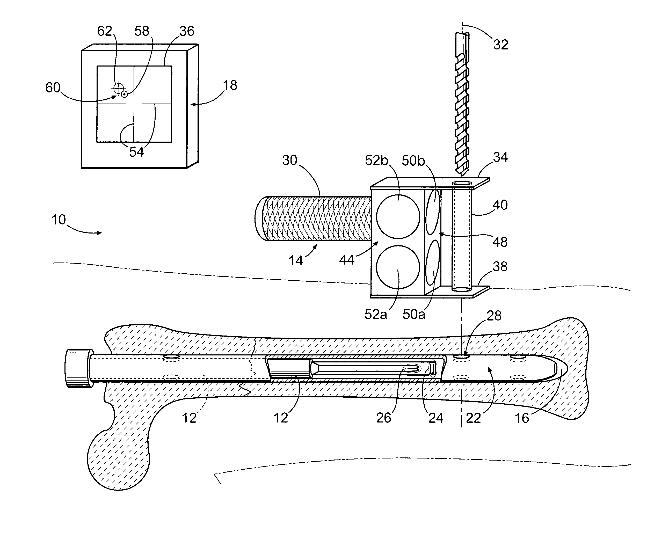
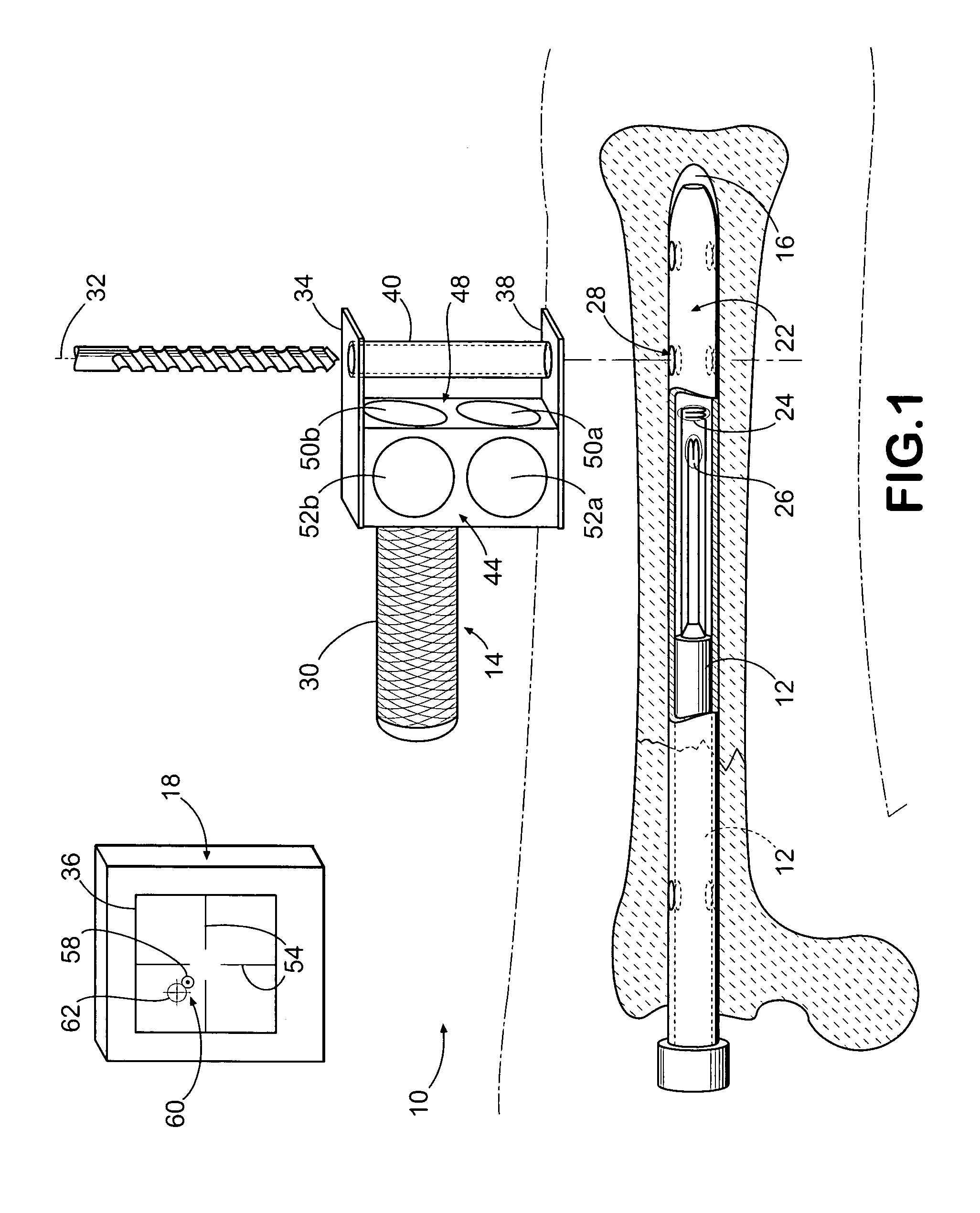
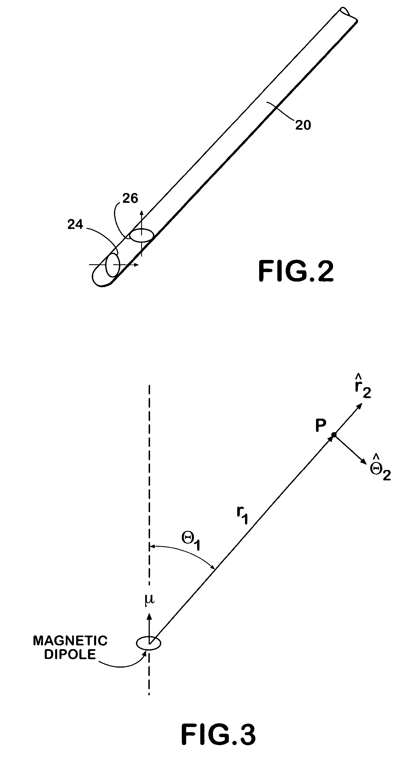
[0029]A system 10 for determining the target point of a drill within a drill bushing is shown in FIG. 1. System 10 is comprised of a probe 12, a handheld guide 14, and a computer 18. As shown in more detail in FIG. 2, probe 12 is comprised of an elongated member 20 to which two drive coils 24, 26 are mounted in orthogonal relationship to one another. The elongated member is typically constructed of main conduit and an integral unit enclosed within a sheath of plastic material with dimensions so that the probe may be inserted in interior passageway 16 of an intramedullary nail 22. Such nails are well-known in the orthopedic field for securing broken bone fragments to one another. The two drive coils may be magnetic dipoles formed by wrapping an electrical conductor around a ferrite core. Preferably, the dipoles are formed by wrapping 201 turns of 44 AWG copper wire around a 1 mm ferrite rod. The drive coils may be fixedly supported within probe 12 or they may be encapsulated within a...


PUM


Abstract

A system that enables axis-to-axis targeting of an instrument placed within a drill bushing includes a computer, a probe, and a pair of sensor planes mounted to a drill bushing so the planes are perpendicular to one another. The probe has two drive coils that may be mounted near its distal end. The two coils are placed close to one another and are oriented so that when they are selectively coupled to an alternating current source they generate magnetic fields that are orthogonal to one another. The computer receives electrical signals from the sensors in the sensor planes and computes target position, bushing alignment, and bushing orientation values. These values may be presented on a display associated with the computer or used to illuminate directional arrows associated with the drill bushing.

Description

FIELD OF THE INVENTION[0001]The present invention relates generally to systems for aligning locking screws with openings in intramedullary nails, and more particularly, to such systems that electro-magnetically align the locking screws with a transverse opening in an intramedullary nail.BACKGROUND OF THE INVENTION[0002]Systems for aligning locking screws in intramedullary nails that have been used to secure fractured bones together are known. A description of a number of such systems is set forth in U.S. Pat. No. 5,411,503, which is expressly incorporated herein in its entirety. These systems may be broadly categorized into three classes: x-ray imaging systems, mechanical systems, and electromagnetic systems. X-ray imaging systems use x-ray imaging to provide an image of the limb being treated with the inserted intramedullary nail so the surgeon may view the transverse hole located in the nail. This image facilitates the surgeon's locating the proper position on the external surface...

Claims


Application Information

Patent Timeline
Patent Type & Authority Patents(United States)
IPC IPC(8): A61B17/58A61B17/17
CPCA61B17/1725A61B17/1707
Inventor HOLLSTIEN, DAVID STUARTHOLLSTIEN, ROY B.
Owner DEPUY PROD INC
Why Eureka
Try Eureka