

Si-containing honeycomb structure and process for production thereof
a honeycomb and si-containing technology, applied in the field of honeycomb structure, can solve the problems of non-uniform temperature distribution, large thermal stress, thermal stress generation, etc., and achieve the effect of improving the thermal conductivity of the honeycomb structure and superior thermal shock resistan
Active Publication Date: 2006-04-18
NGK INSULATORS LTD
View PDF17 Cites 27 Cited by
- Summary
- Abstract
- Description
- Claims
- Application Information
AI Technical Summary
Benefits of technology
[0007]The present invention has been made in view of the above situation. The present invention aims at providing a h
Problems solved by technology
In the honeycomb structure used for such a purpose, the sharp temperature change of exhaust gas and the local heating makes non-uniform the temperature distribution inside the honeycomb structure and there have been problems such as thermal stress generation in honeycomb structure, crack formation and the like.
When the honeycomb structure is used particularly as a filter for capturing a particulate substance in
Method used
View moreImage
Smart ImageViewing Examples

Examples
 PUM
| Property | Measurement | Unit |
|---|---|---|
| Lattice constant | aaaaa | aaaaa |
| Percent by mass | aaaaa | aaaaa |
| Percent by mass | aaaaa | aaaaa |
Abstract
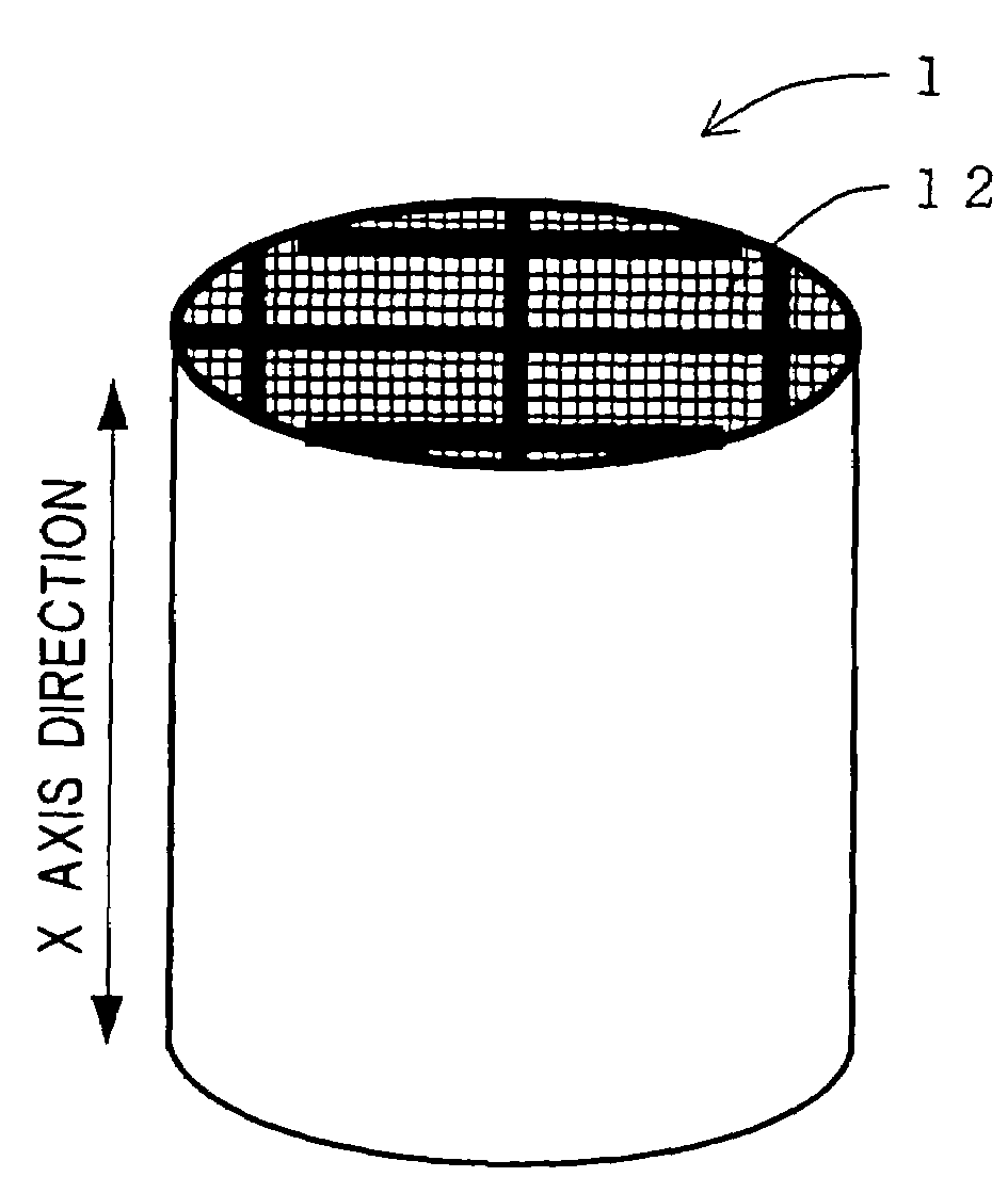
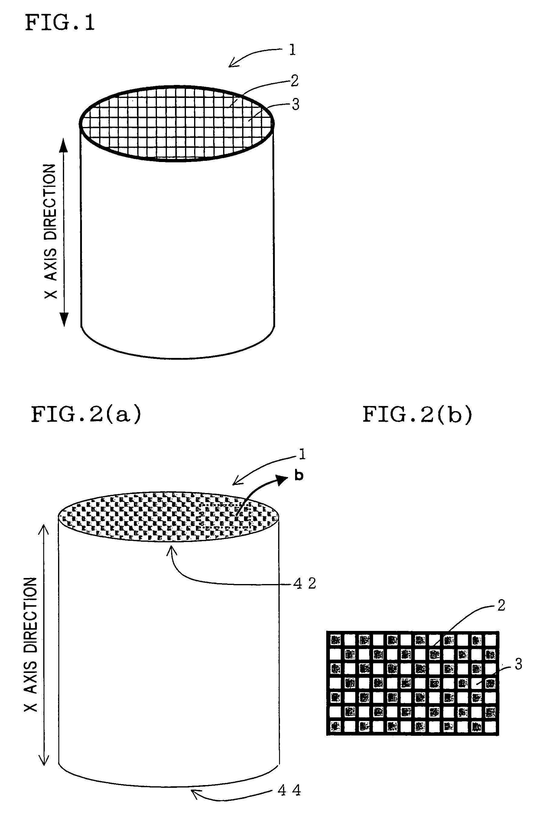
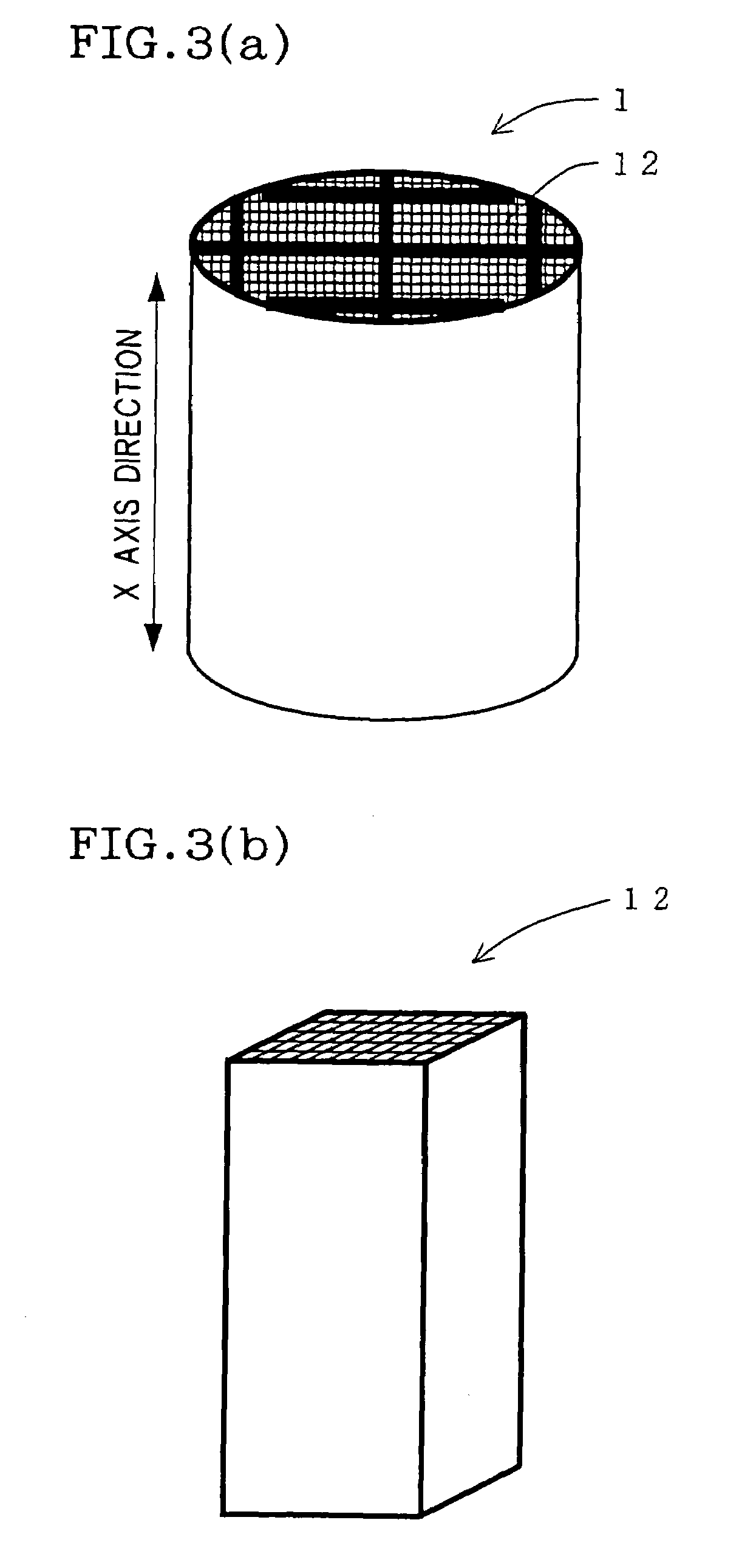
A honeycomb structure 1 has a large number of through-holes 3 divided by partition walls 2 and extending in the axial direction, characterized in that the honeycomb structure contains a Si phase having a lattice constant controlled at 0.54302 to 0.54311 nm at room temperature. A process for producing the honeycomb structure 1, includes a firing step of firing a precursor of honeycomb structure, wherein the precursor contains a Si phase and the firing step is conducted using a furnace material free from any boron-containing compound. A process for producing the honeycomb structure 1, includes a firing step of firing a precursor of honeycomb structure, wherein a reduction percentage of Si content in Si phase after firing step relative to Si content in Si phase before firing step is suppressed at 10% by mass or less. Having an improved thermal conductivity, the honeycomb structure is superior in thermal shock resistance.
Description
TECHNICAL FIELD[0001]The present invention relates to a honeycomb structure used, for example, in a filter for capturing fine particles present in an exhaust gas emitted from an internal combustion engine, a boiler or the like, or in a catalyst carrier, as well as to a process for producing the honeycomb structure. More particularly, the present invention relates to a honeycomb structure superior in thermal conductivity and a process for production thereof.BACKGROUND ART[0002]Honeycomb structures are in use, for example, in a filter for capturing fine particles present in an exhaust gas emitted from an internal combustion engine, a boiler or the like, particularly diesel fine particles, as well as in a carrier for exhaust gas purification catalyst.[0003]Honeycomb structures used, for example, as a filter generally have, as shown in FIGS. 2(a) and 2(b), a large number of through-holes 3 divided by partition walls 2 and extending in the X-axis direction, wherein each through-hole 3 is...
Claims
Login to View More Application Information
Patent Timeline
 IPC IPC(8): B01D39/20C04B38/00F01N3/02B01D46/24B01J21/08B01J27/224B01J35/04B01J37/08B01J37/34B28B3/26C04B35/117C04B35/185C04B35/488C04B35/505F01N3/022F01N3/28
CPCB01D39/2075B01D46/247B01J21/08B01J27/224B01J35/04C04B35/117C04B35/185C04B35/488C04B35/505C04B35/565C04B35/581C04B38/0006F01N3/0222F01N3/2828B01D46/0001Y02T10/20B01D46/2466B01D2279/30B01J37/08B01J37/346C04B2111/00793C04B2111/0081C04B2235/3821C04B2235/3826C04B2235/386C04B2235/422C04B2235/428C04B2235/5436C04B2235/668C04B2235/72C04B2235/761C04B2235/77C04B2235/80C04B2235/9607F01N2330/06Y02T10/12F01N3/022B01D46/2425
InventorICHIKAWA, SHUICHIHARADA, TAKASHIOTSUKA, AIKOWADA, YUKIHISAYAMAMOTO, YOSHINORI
OwnerNGK INSULATORS LTD